Game Gear VA0 - 4
Console status
| Date | Power | Sound | RLB | Game operation | Screen |
|---|---|---|---|---|---|
| 2024/06/22 | ✔️ | ✔️ | ✔️ | ✔️ | ⚠️ |
| 2024/06/24 | ⚠️ | ✔️ | ✔️ | ✔️ | ⚠️ |
| 2025/04/25 | ✔️ | ✔️ | ✔️ | ✔️ | ⚠️ |
Console details
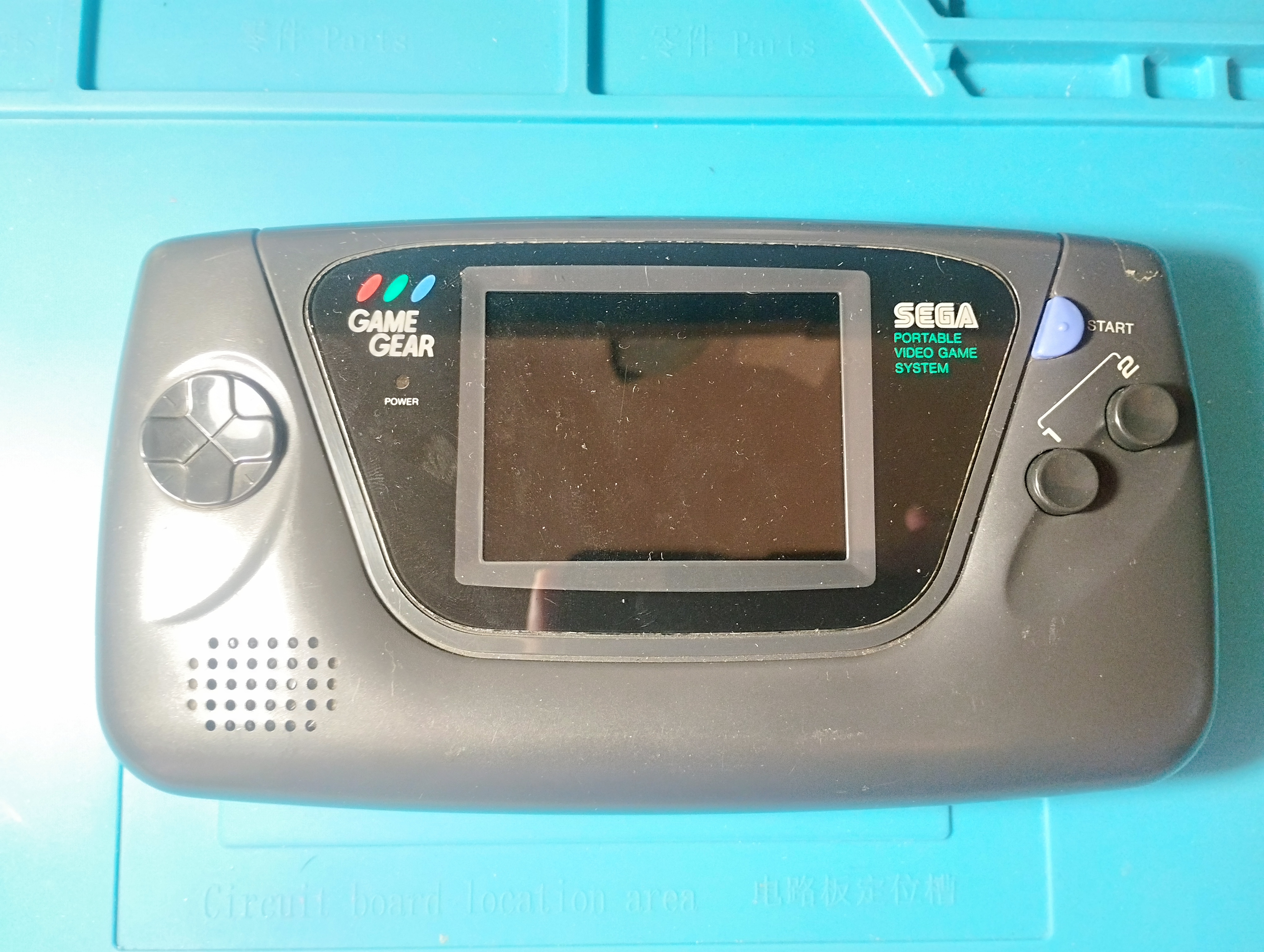
- Japanese Game Gear bought during my trip to Japan on August 2023
- The screen protector was already replaced but the console seemed unmodified (screws were tight and capacitors were the stock ones)
Specs
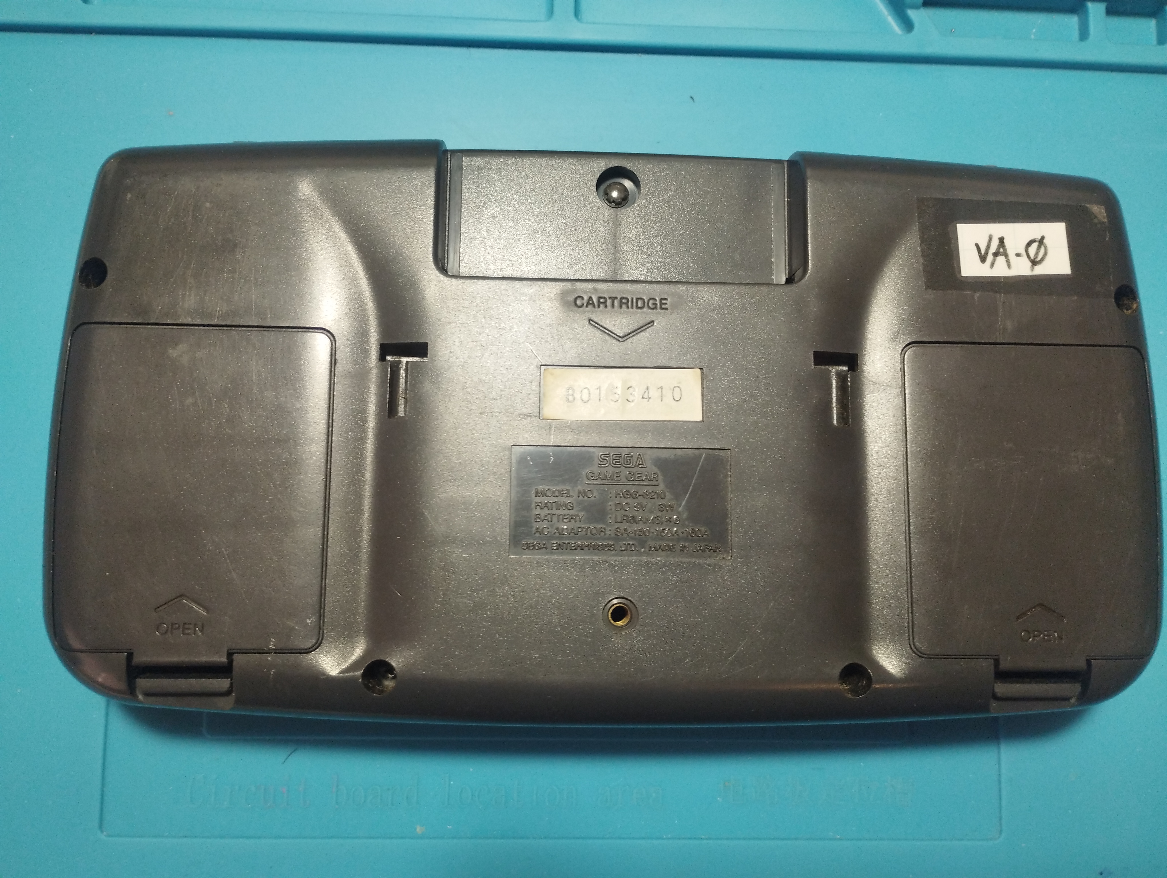
- Model Number: HGG-3210
- Serial Number: B0153410
- Main board: 837-7398-01 (Twin ASIC)
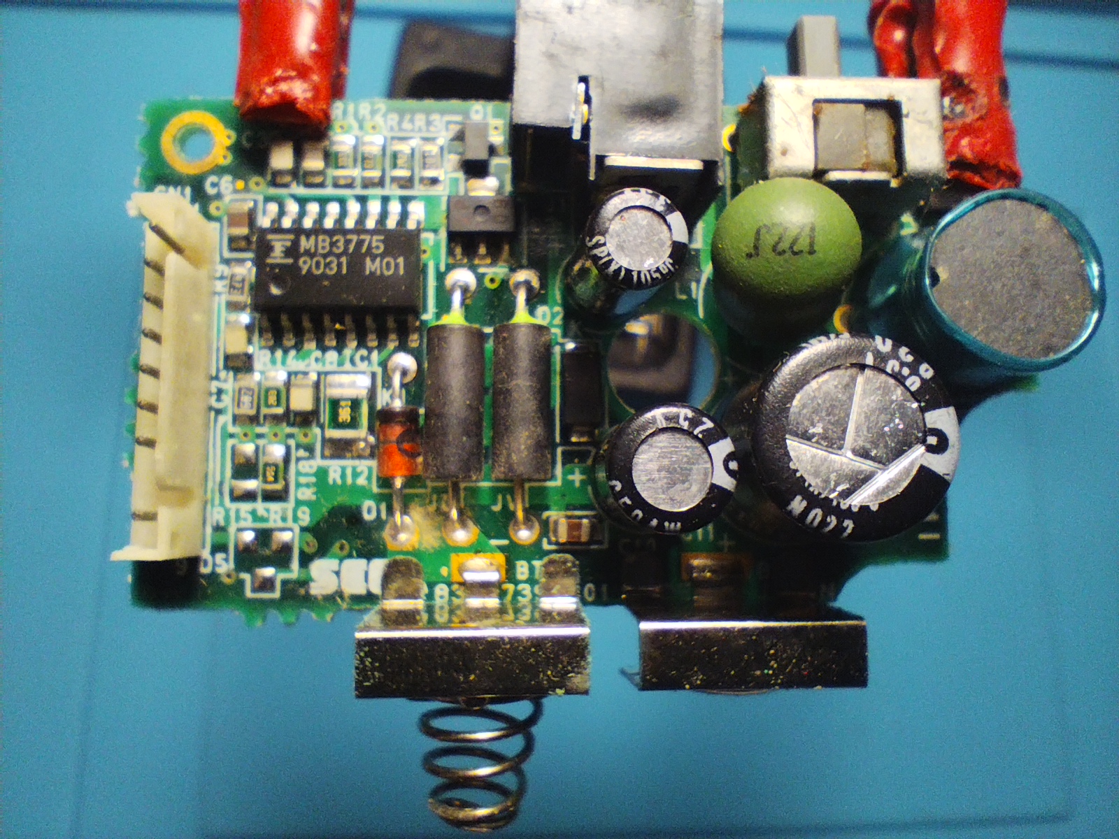
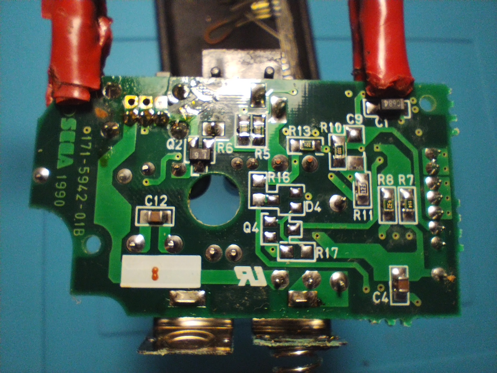
- Power board: 837-7399-01 (Board says 171-5942-01B)
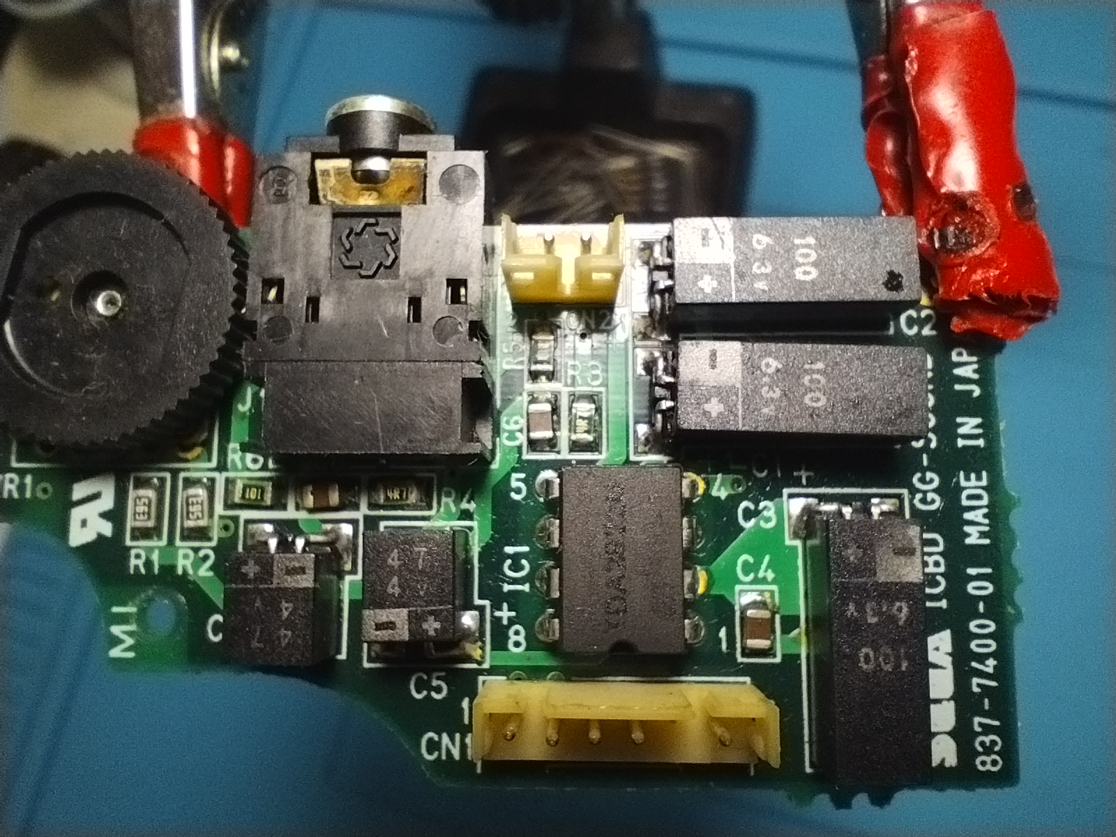
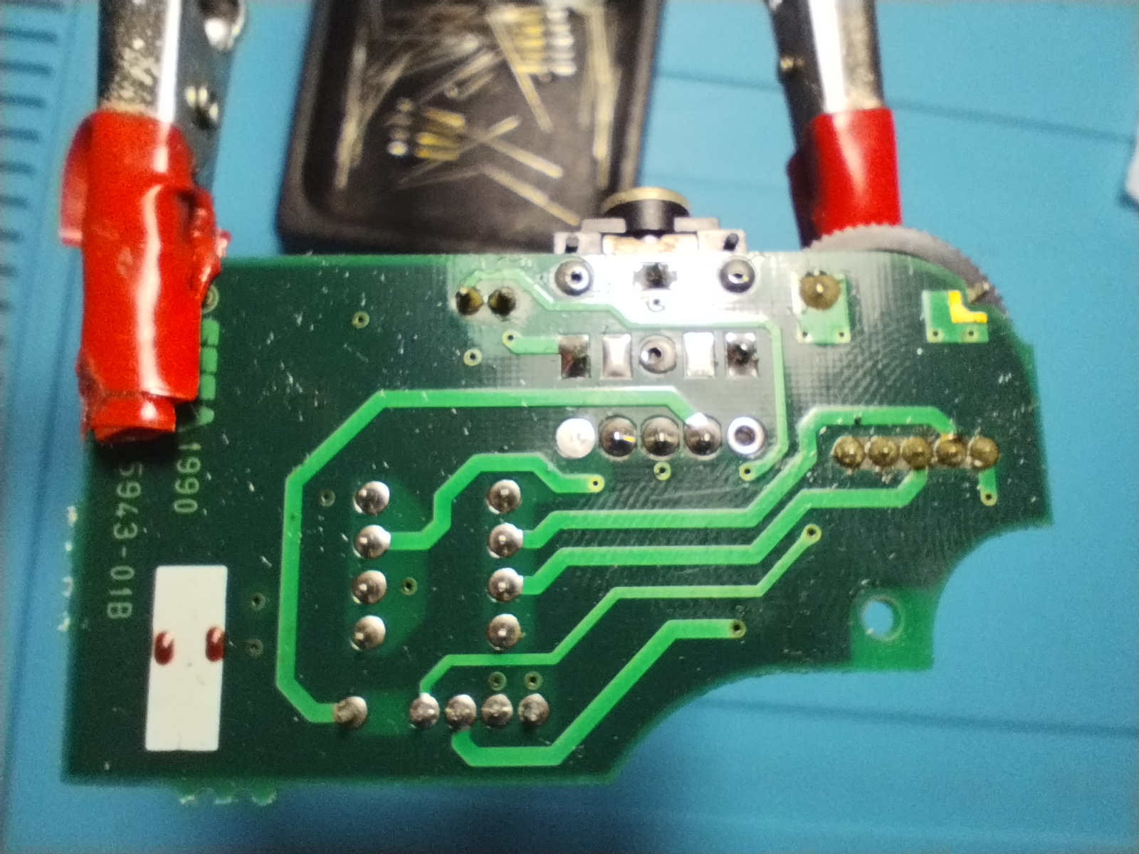
- Audio board: 837-7400-01 (Initial release Japanese Game Gear with square-body surface mount caps similar to GG main boards)
Overview
First boot
- Power LED doesn’t turn on
- The screen doesn’t turn on and there’s no sound either
Visual inspection
Outside
The outside has visible scratches from usage but no cracks
Main board
Front side
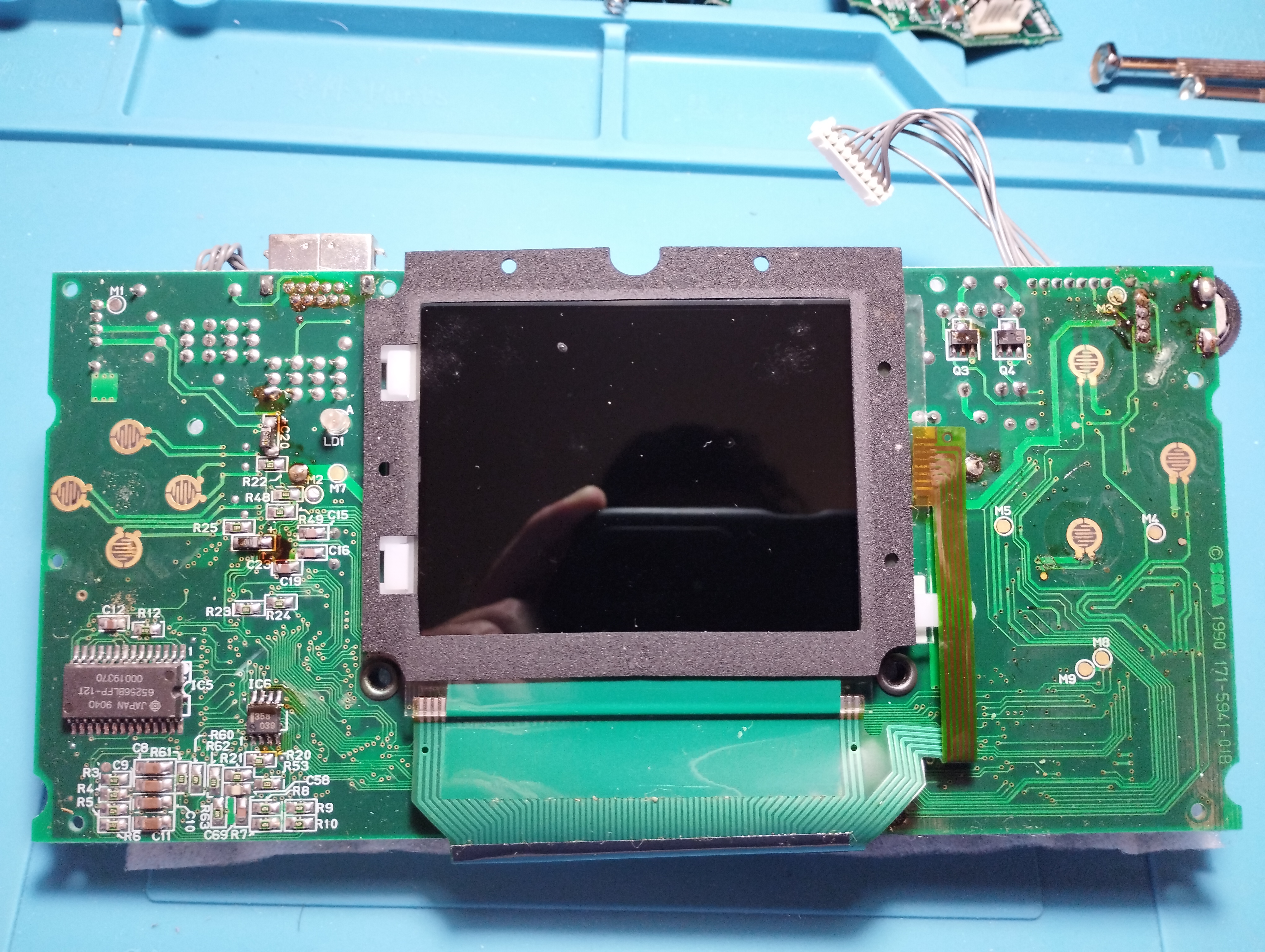
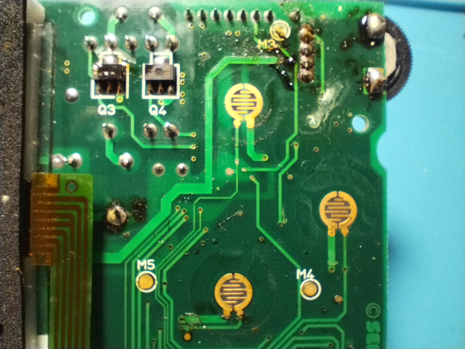
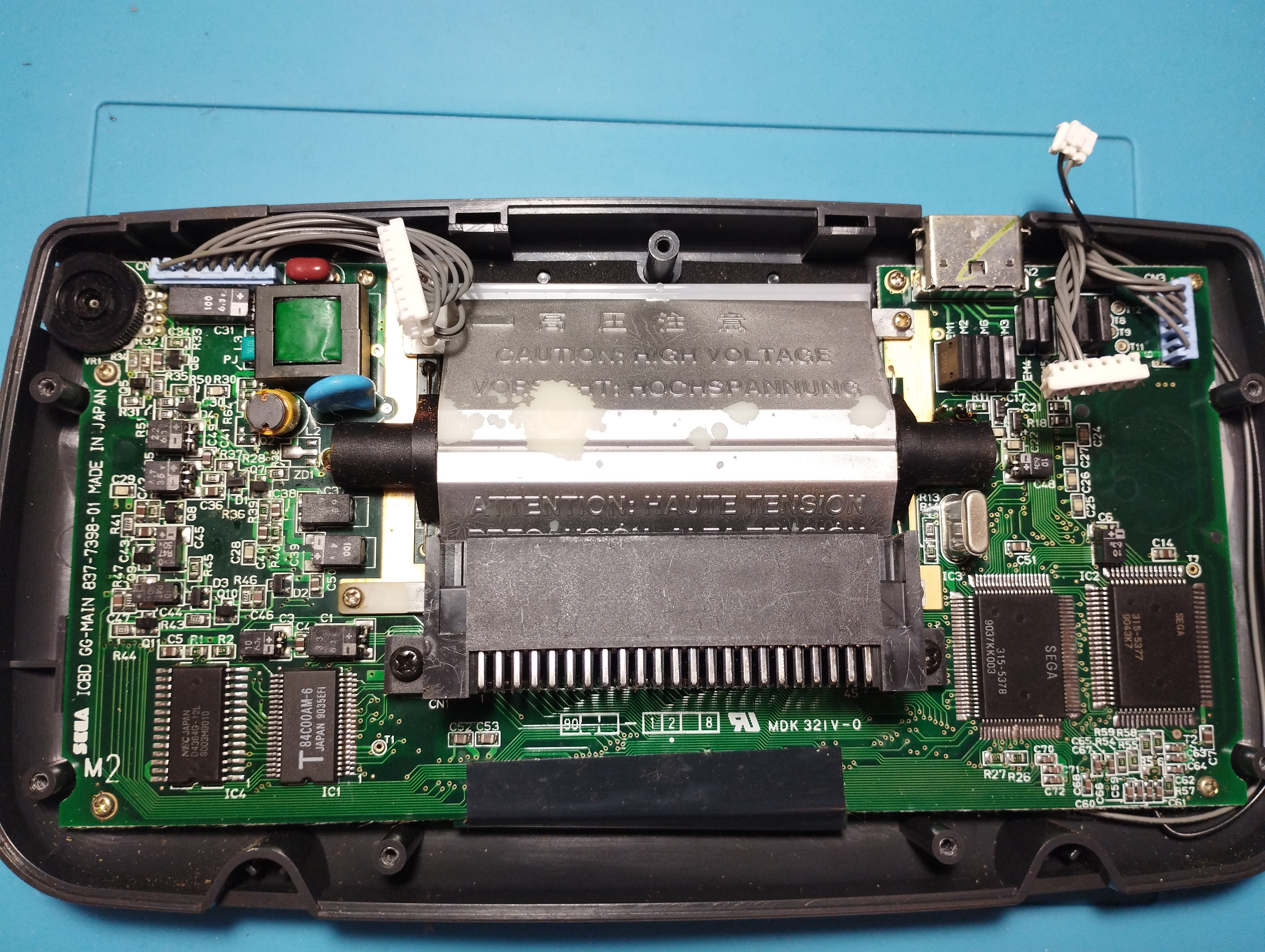
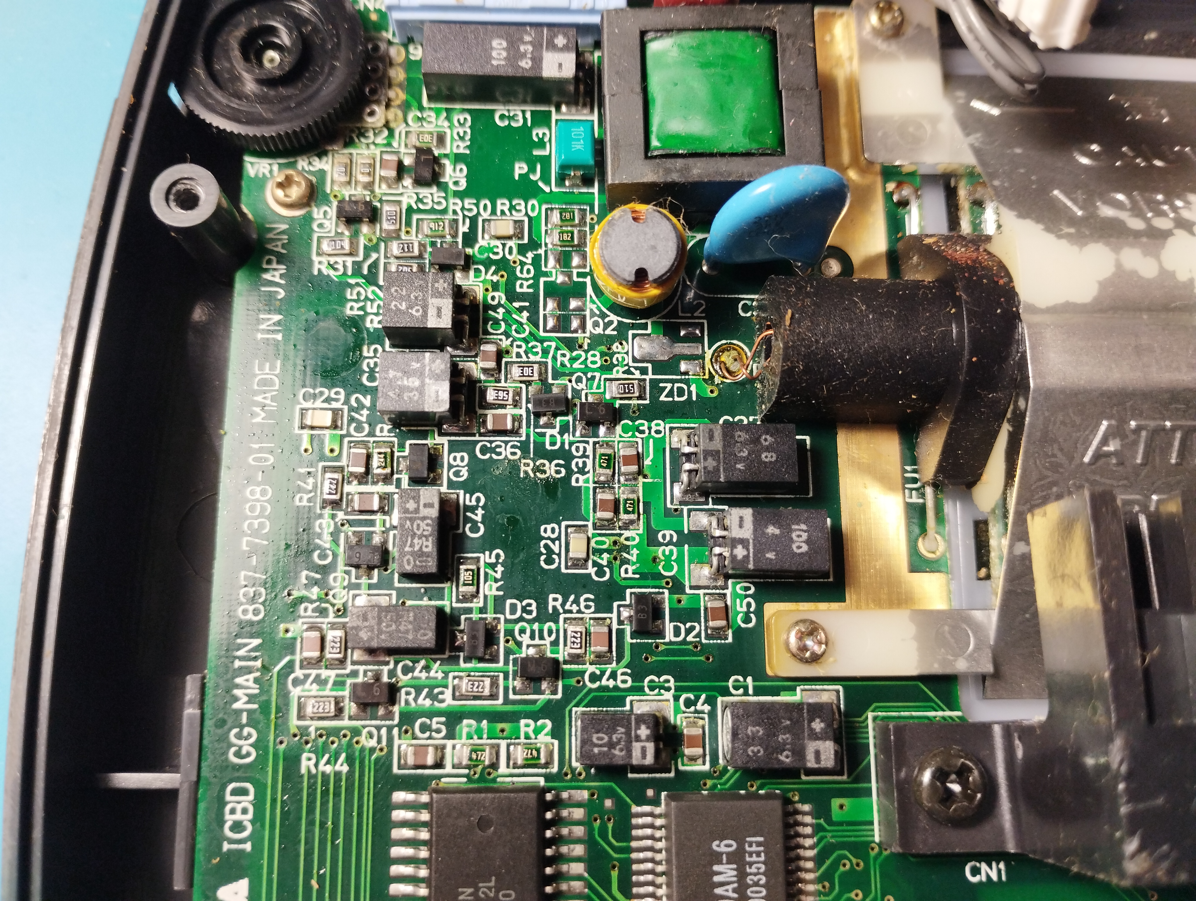
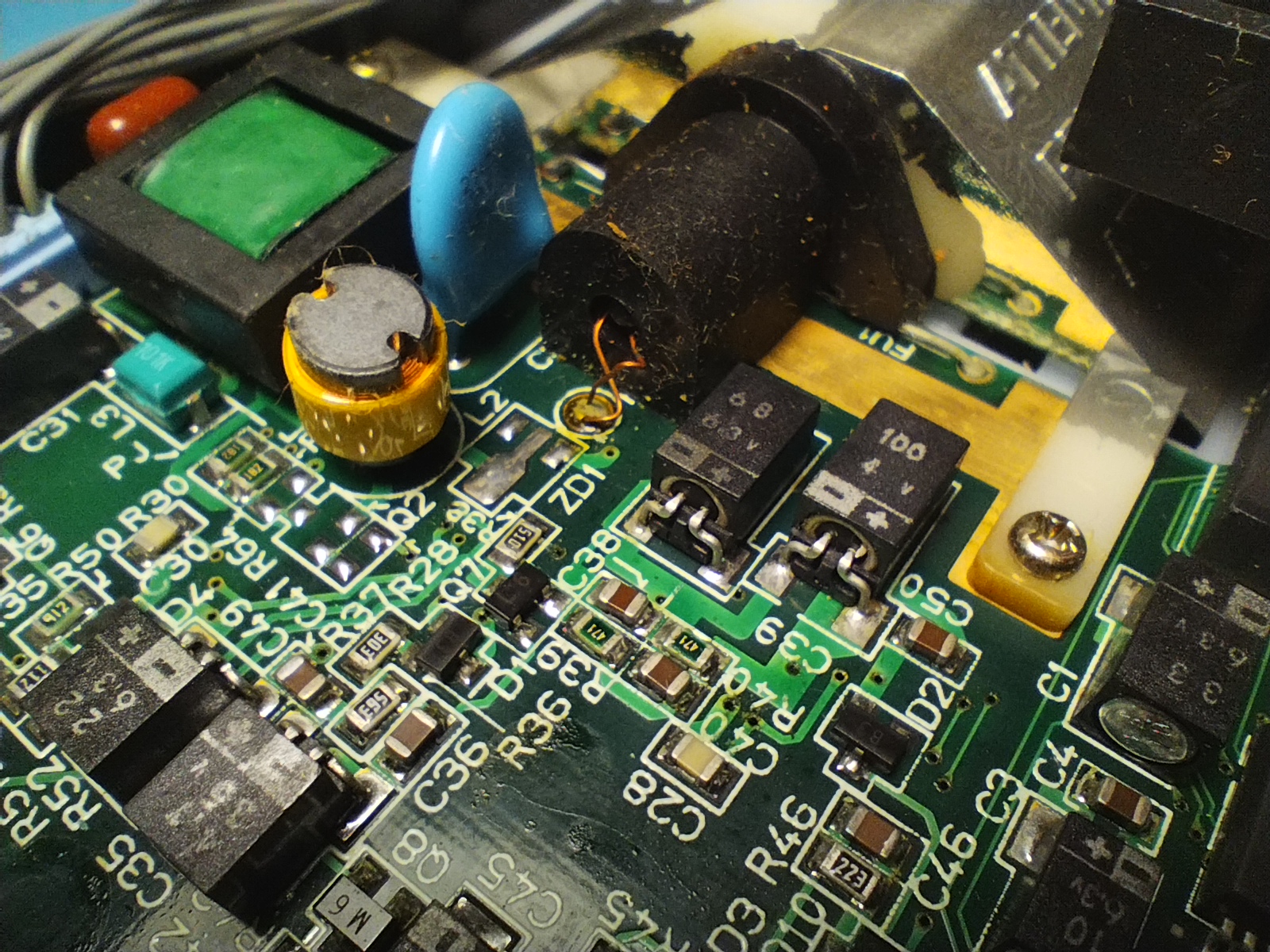
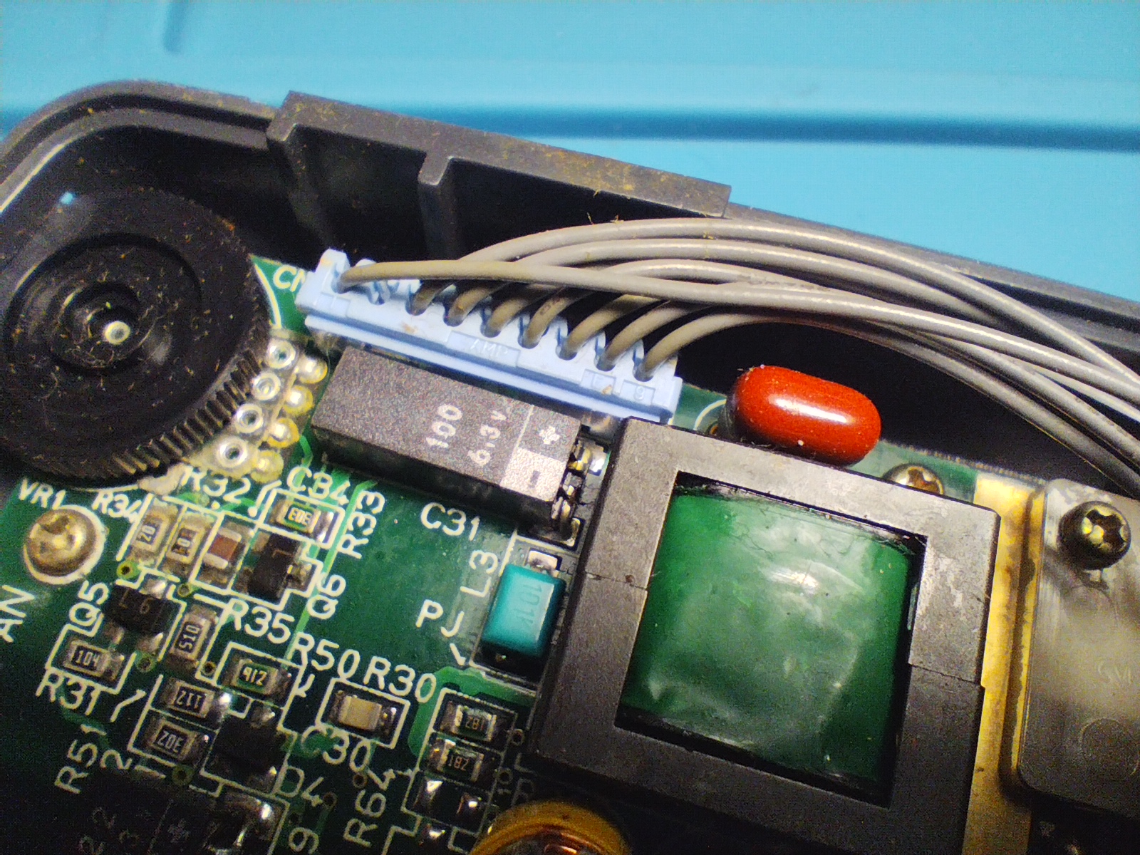
Some flux residues from factory and visible corrosion in brightness wheel contacts and vias
Rear side
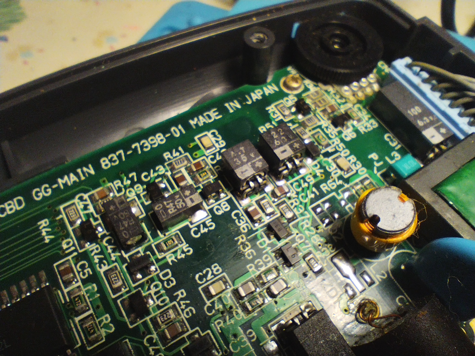
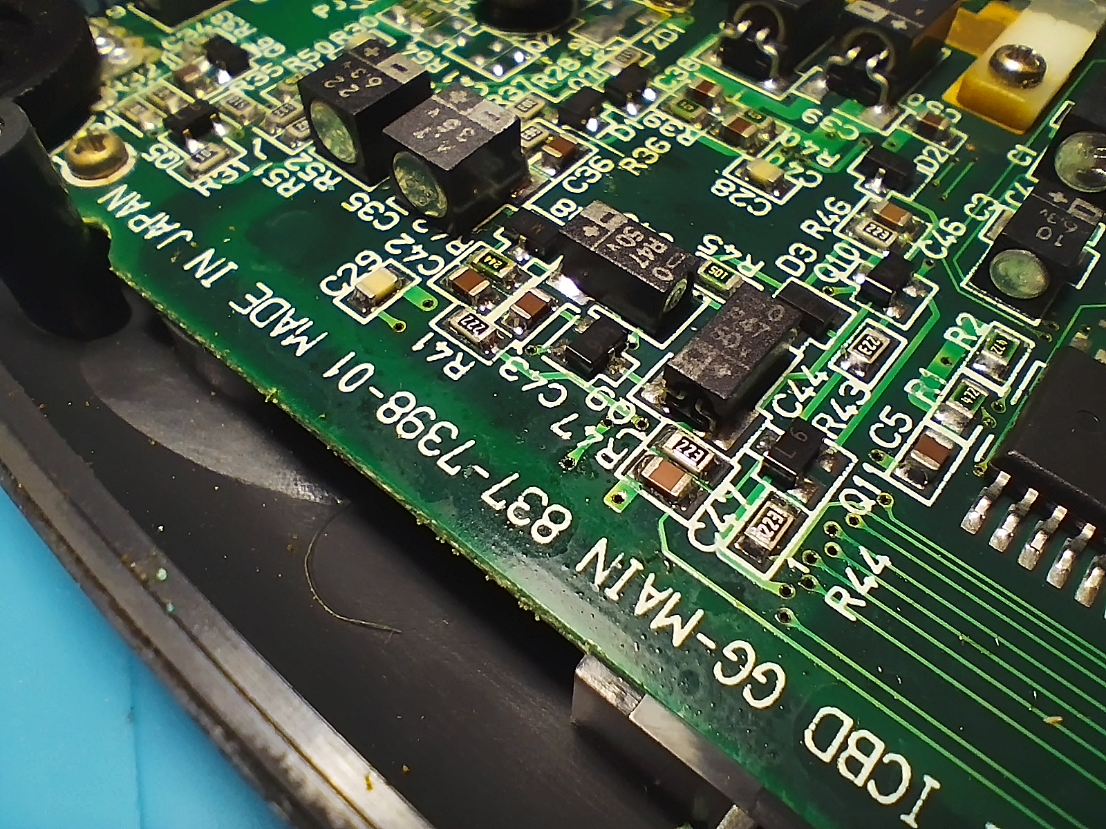
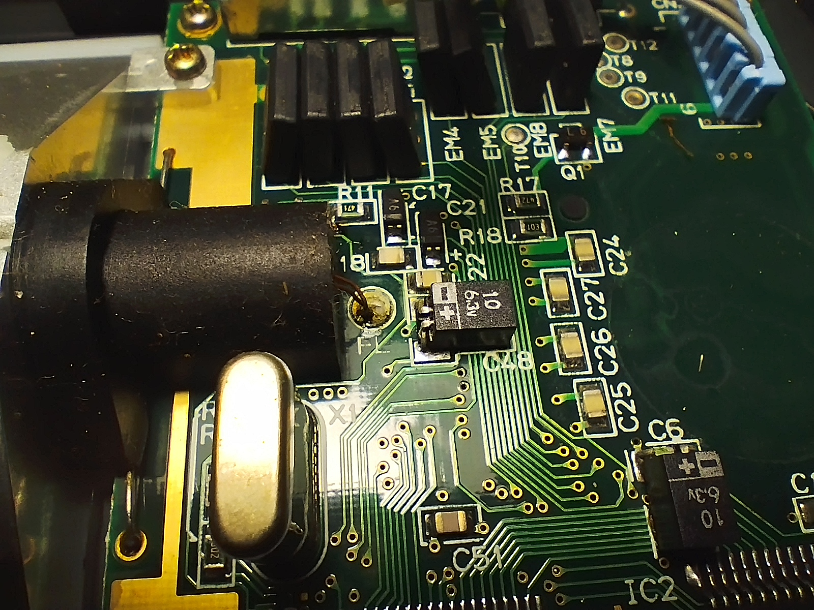
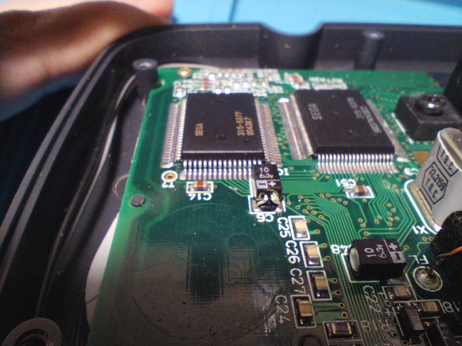
There are no visible leaks on capacitors but vias seem corroded, so extreme precautions when removing and cleaning the pads.
Power board
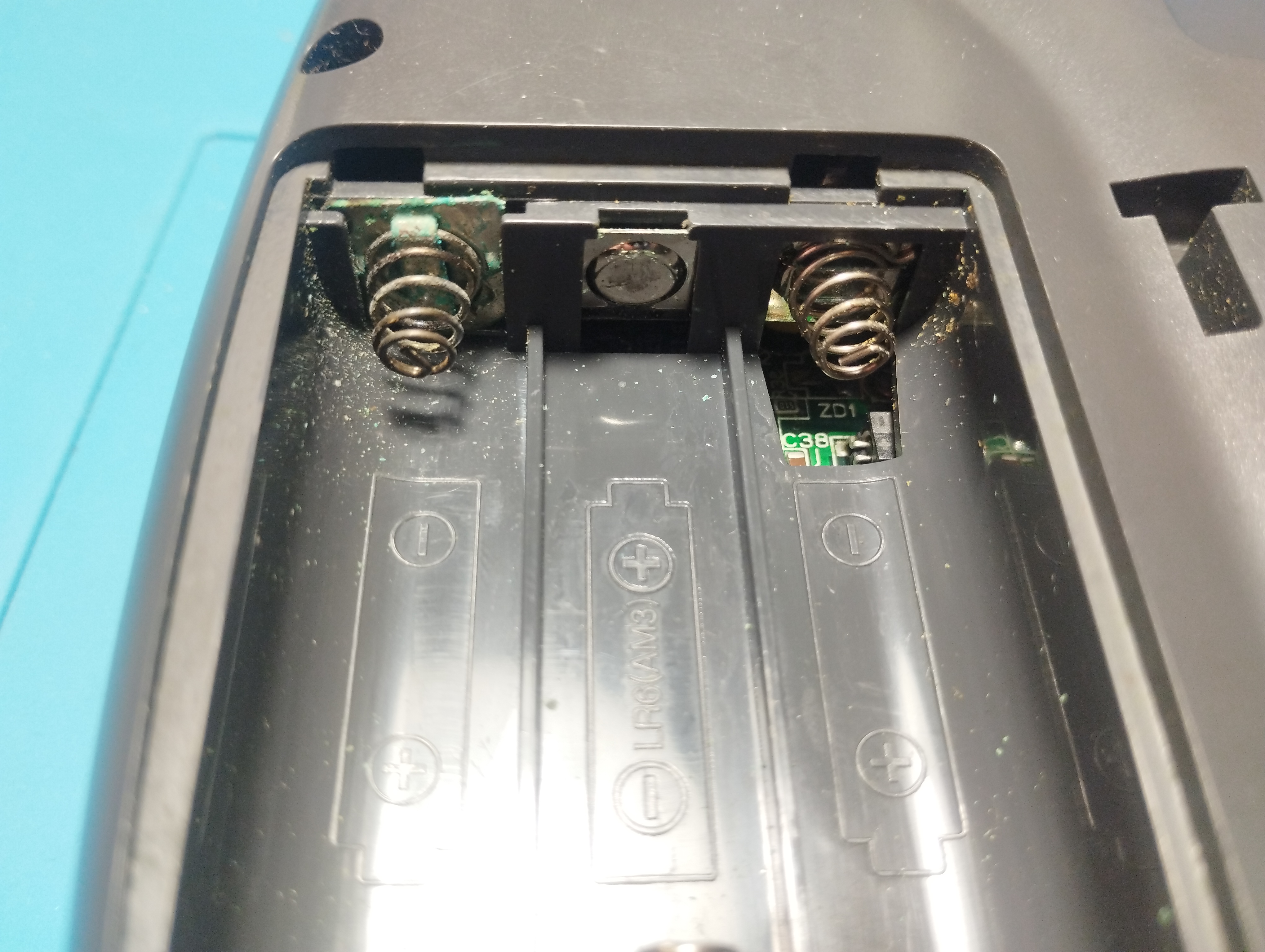
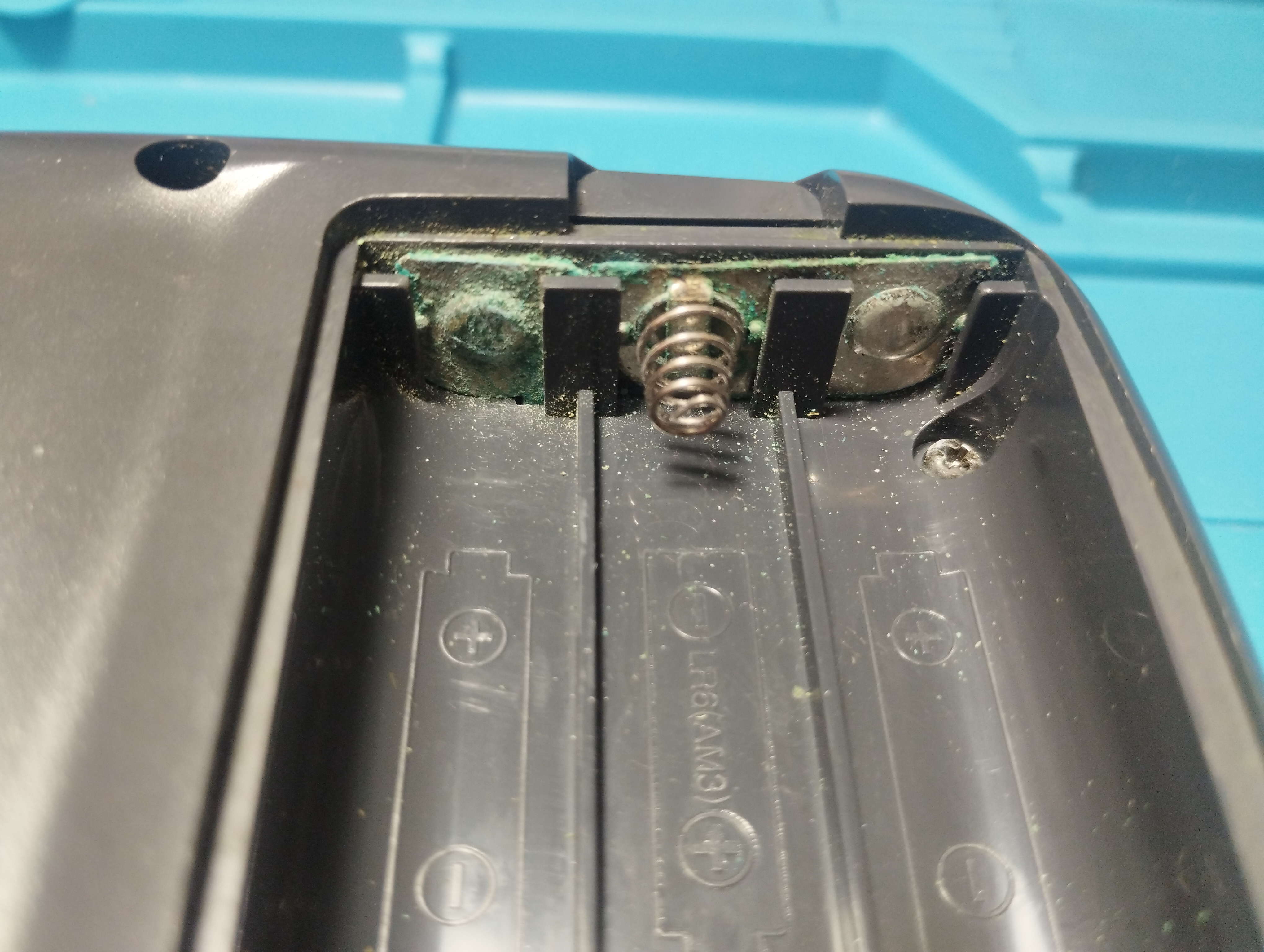
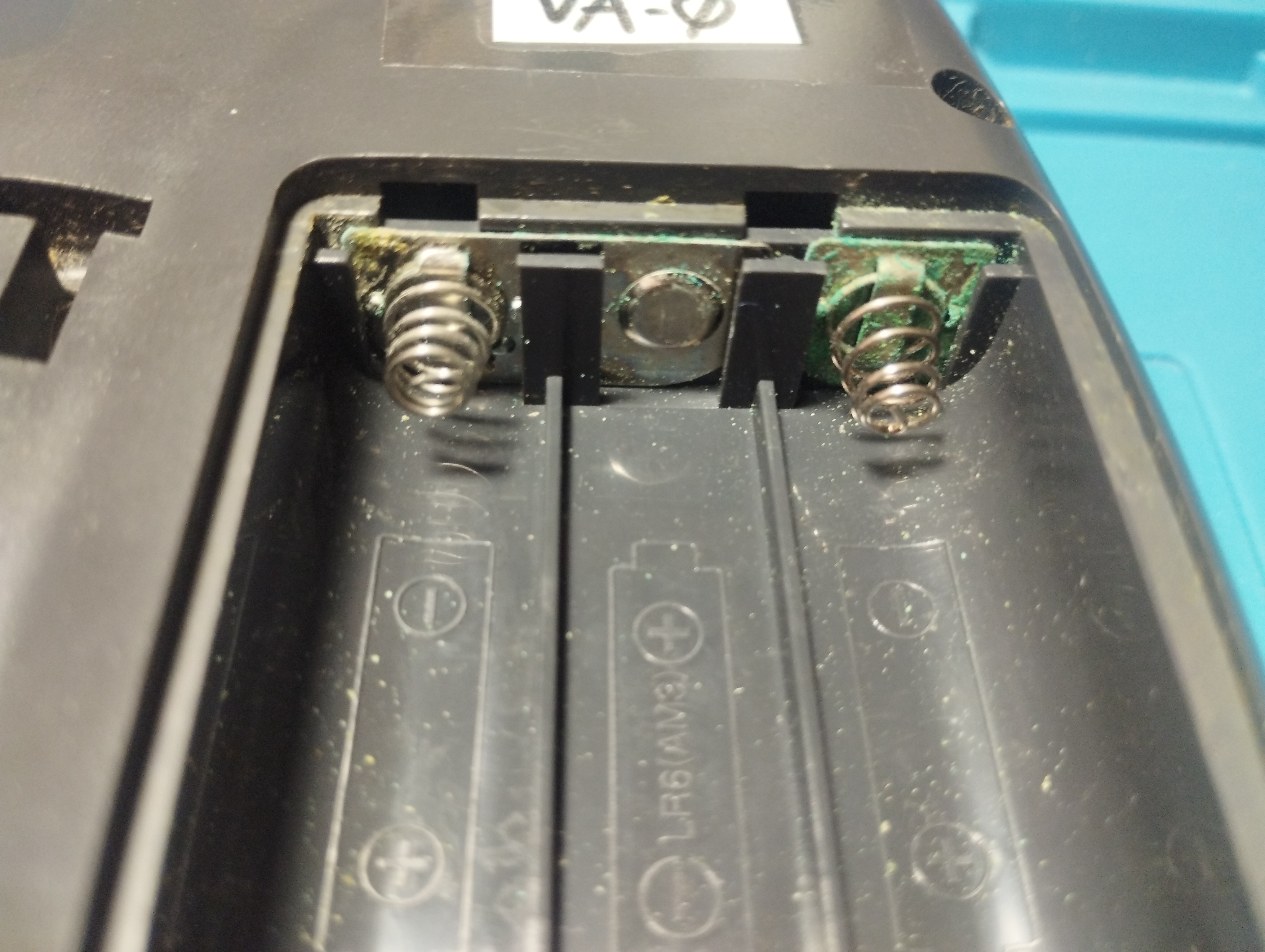
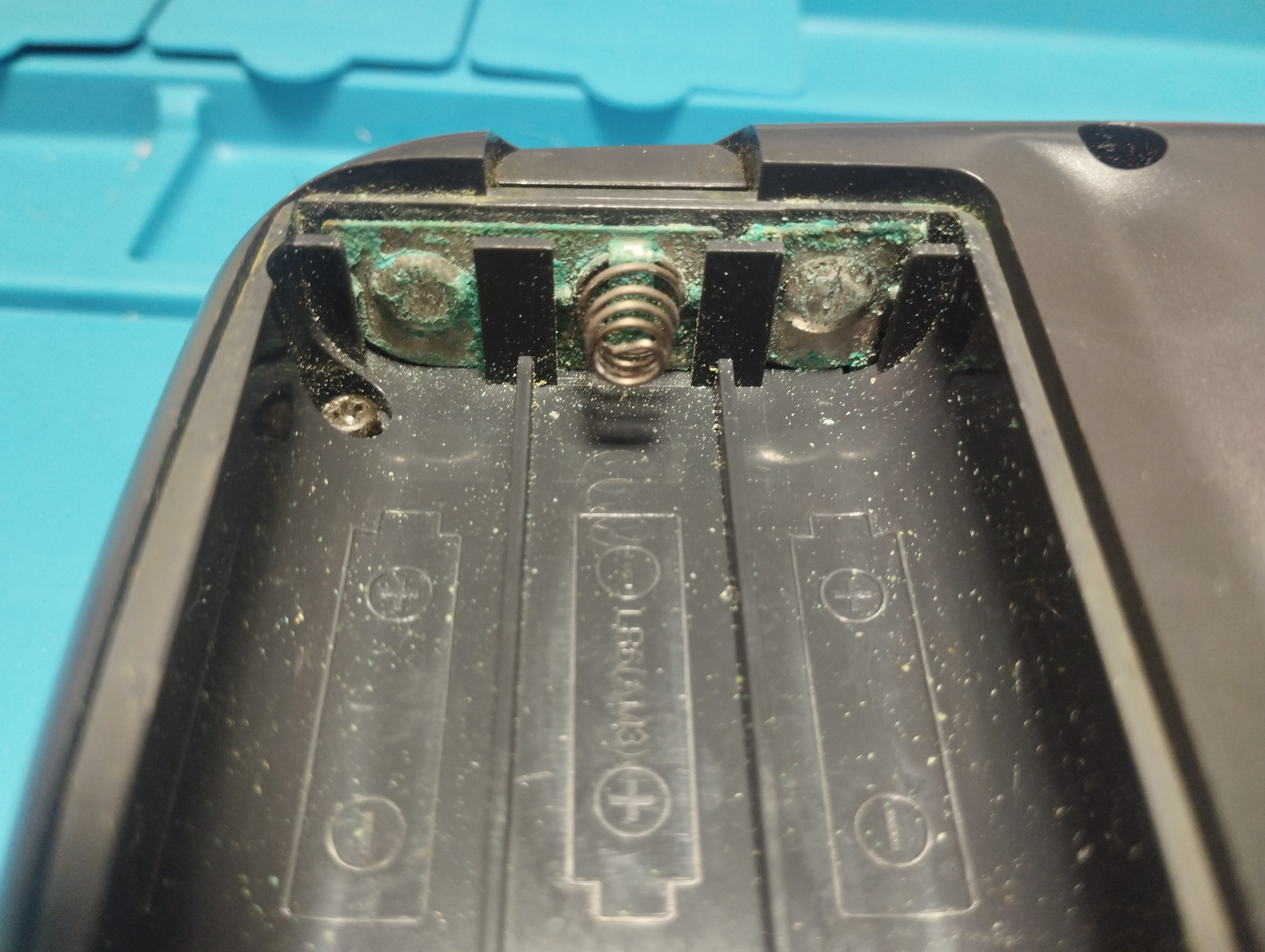
Some corrosion in battery contacts.
Audio board
Visible leakage and corrosion in some contacts.
Battery contacts
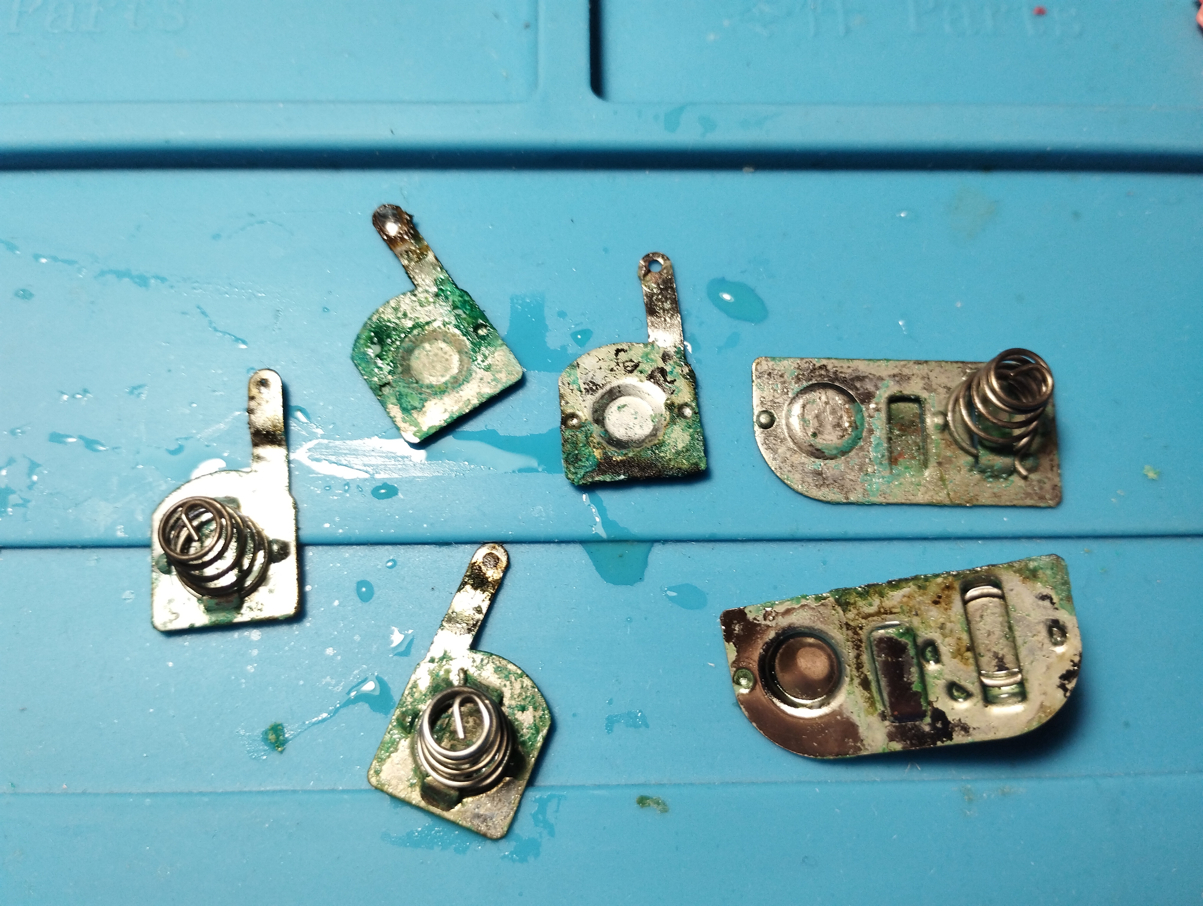
Huge corrosion in springs and plates
Maintenance
2024/06/22: Recap
Following Retrosix’s wiki, the capacitors are replaced like this:
Power board
- A voltage check on the power board shows that 5V network outputs 5V at first but keeps draining until reaching 0V after some seconds
- Capacitors are replaced with new electrolytic ones with the same rating
- The only exception is the 820uF/6.3V one that has been replaced with a solid electrolytic capacitor of the same rating (does it make any difference compared to the standard electrolytic ones?)
- According to the data sheet, solid electrolytic capacitors have a low ESR and high ripple current
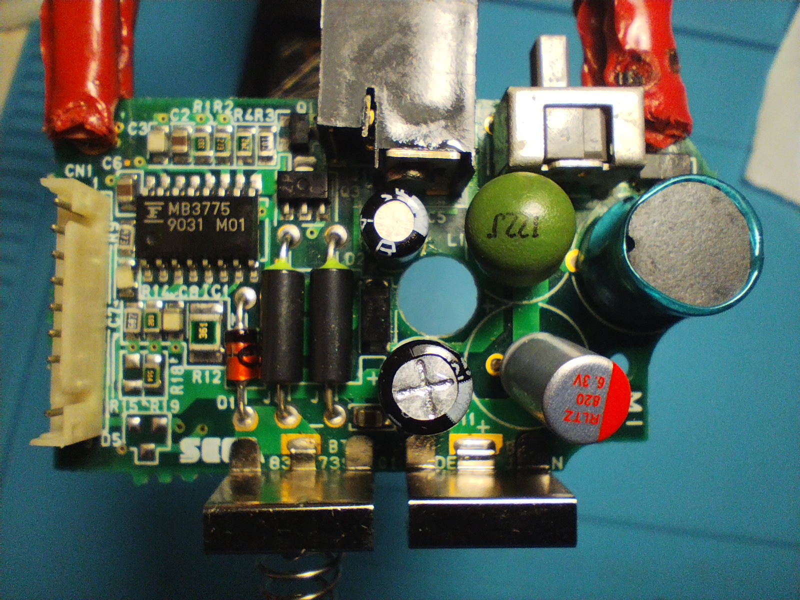
Removing some capacitors proved to be quite challenging, even with an electrical desoldering pump. The trick to keep the vias intact is to reapply new solder several times to mix old solder with new one. Flux is indispensable to help transfer heat on already old and dry solder as well!
If a leg is stubbornly stuck, use some desoldering wick with new solder and a lot of flux to remove the excess inside the via by capilarity. Rinse and repeat until the leg is free!
Also use the desoldering wick to free the hole from solder before putting the new capacitors.
Audio board
- All capacitors are replaced with 100uF/10V ceramic capacitors
- C1 positive pad has been literally destroyed by corrosion. The new capacitor is soldered directly to the trace by exposing it a little bit
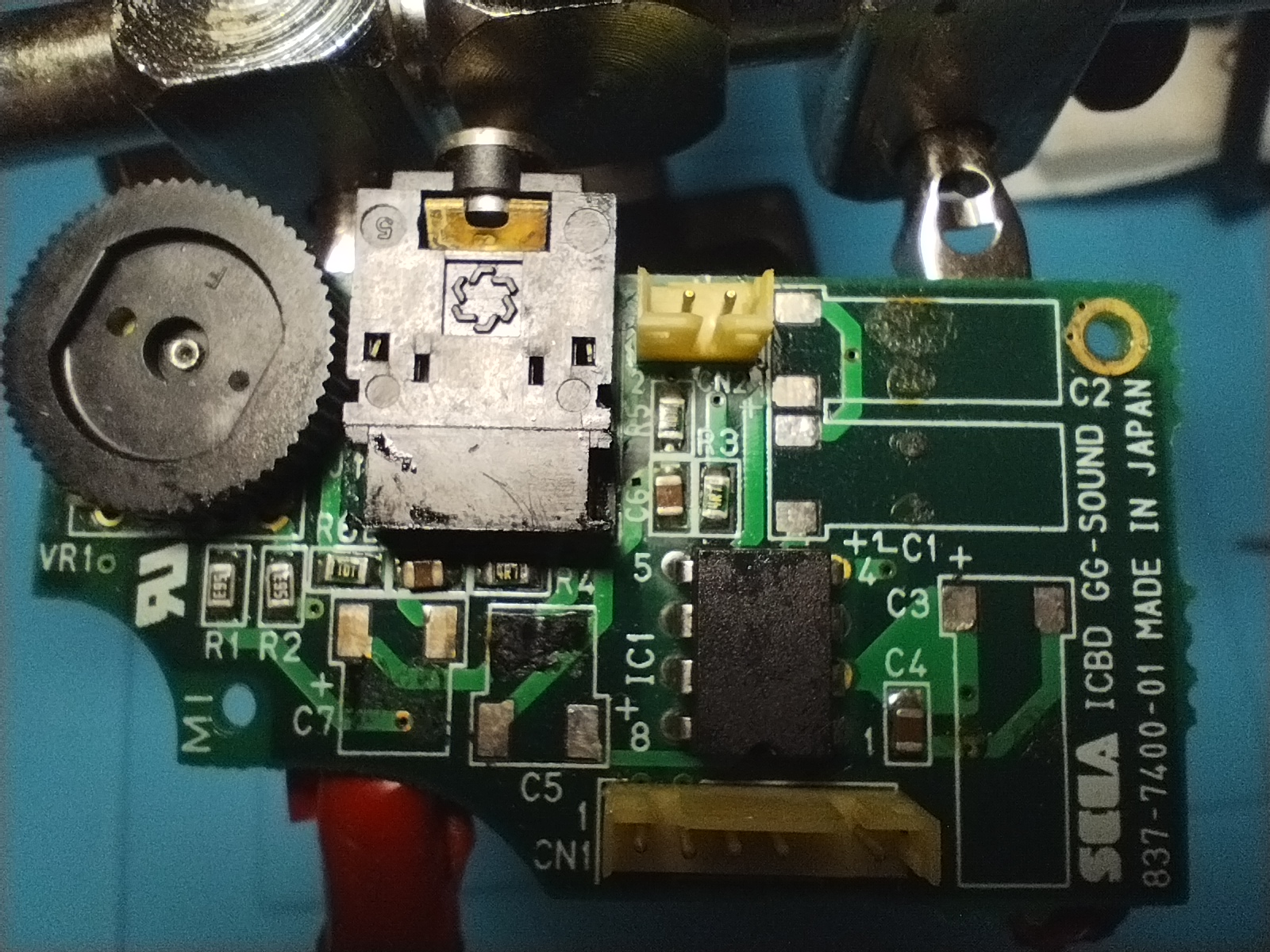
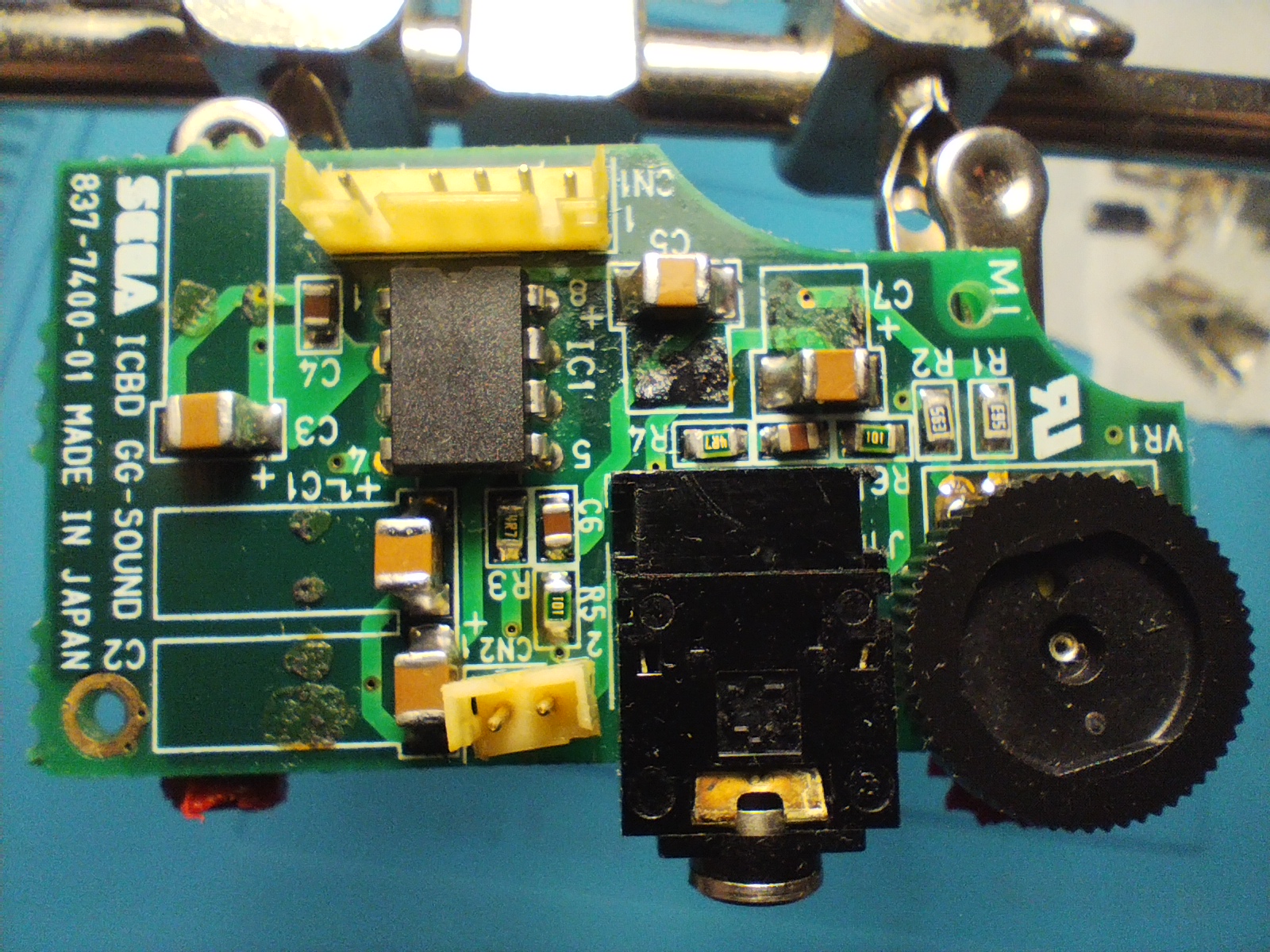
Removing these surface-mount capacitors without proper care can damage the underlying pads and vias. The trick to keep the pads intact is to reapply new solder to mix old solder with new one. Flux is indispensable to help transfer heat on already old and dry solder as well!
Prior to dettach the capacitor from the board, use the desoldering wick to remove as much solder as possible between the pad and the capacitor leg. This will help reduce mechanical stress on the pad when snapping the glue beneath the capacitor.
Main board
Following RetroSix Wiki advises, all capacitors have been first removed and then checked if the console reaches the Red Light Boot (RLB) state:
Components Needed for RLB
It’s worth noting that audio ICs, every aluminium capacitor, the LCD, MPU, Work RAM nor Video RAM or main crystal are involved or even needed to be soldered on the board to get to red light boot. Don’t waste your time on those until you get red light.
Prior to dettach the capacitor from the board, use the desoldering wick to remove as much solder as possible between the pad and the capacitor leg. This will help reduce mechanical stress on the pad when snapping the glue beneath the capacitor.
With the capacitors removed, both power board and audio board are re-connected and the console is powered up again:
- Power LED turns on and keeps lighted up
- Fluorescent tube also lights up but the screen doesn’t show any image
- Audio also works when putting a cartridge
Once verified that the console reaches the RLB state, it’s time to solder the new capacitors. As with the previous VA-0 B0126683, these are the ceramic capacitors characteristics:
- All original capacitors rated lower than 1uF are replaced with 1uF/50V ceramic capacitors
- All original capacitors rated lower between 1uF and 10uF are replaced with 10uF/50V ceramic capacitors
- All original capacitors rated higher than 10uF are replaced with 100uF/10V ceramic capacitors
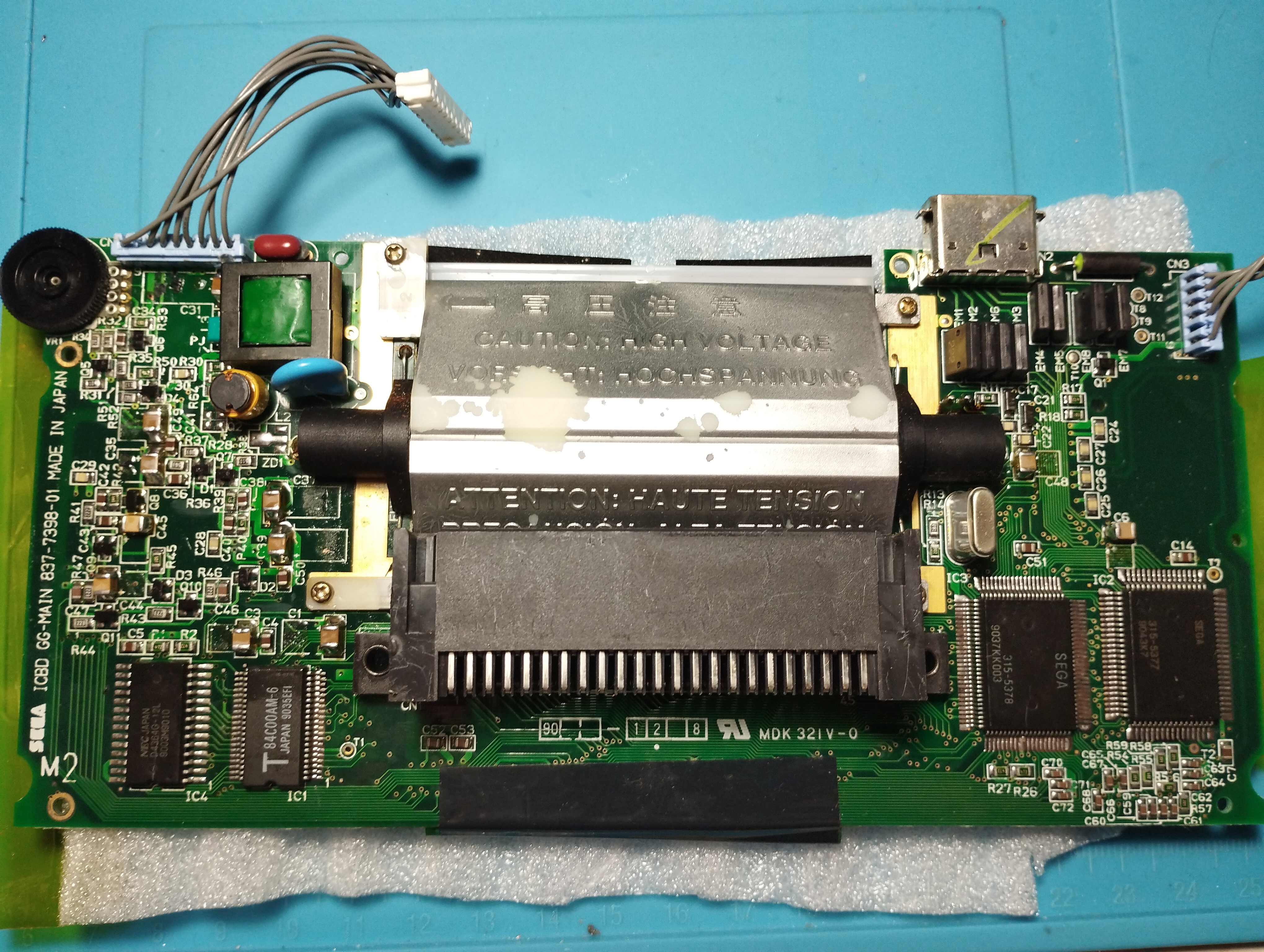
- C31 capacitor is always hard to deal with and the power connector has melted a little bit, but with the desolder wick trick the pads were intact after removal
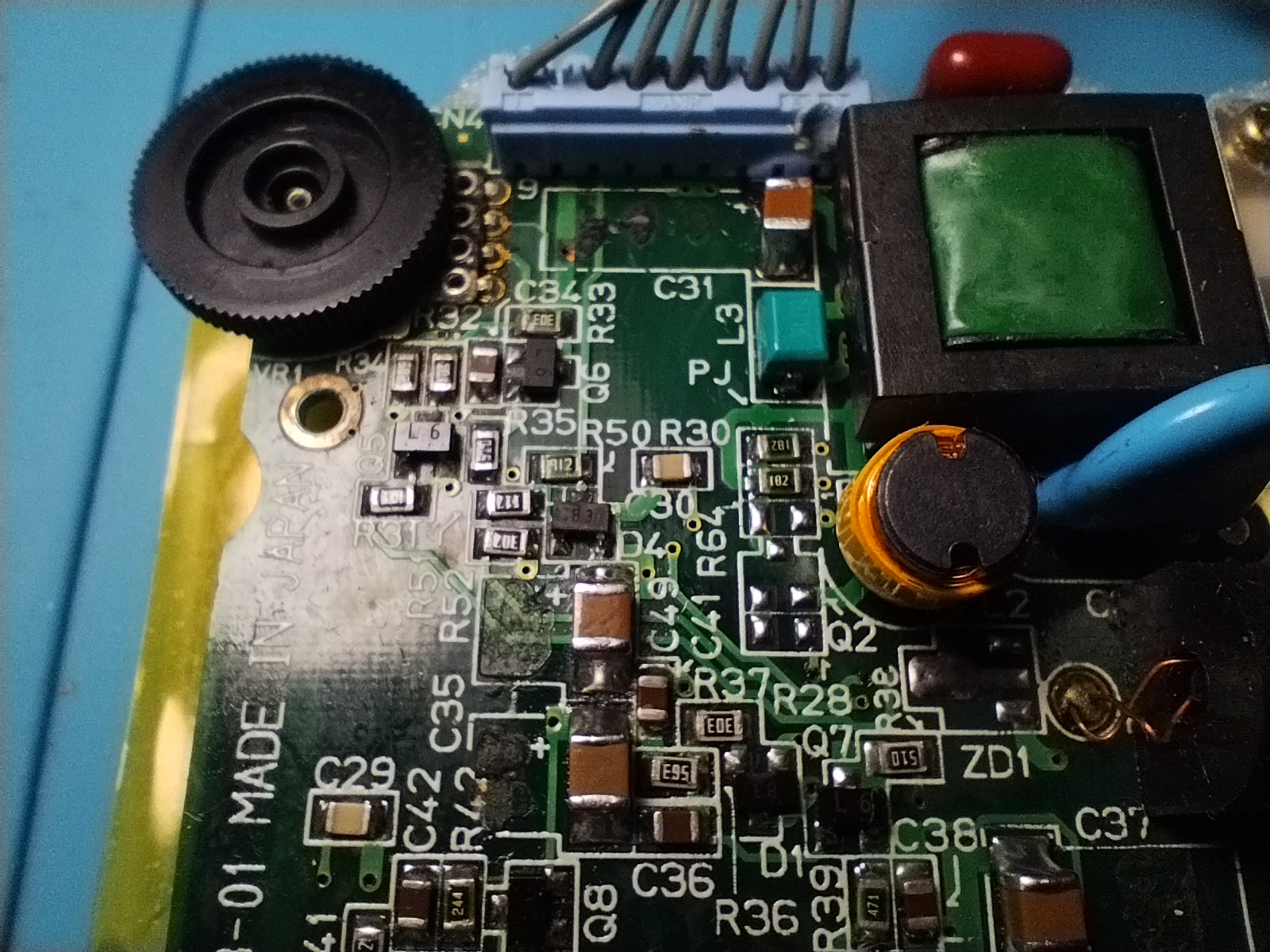
- The rest of the left side capacitors didn’t present any issue when removing and replacing them, and the result is pretty clean
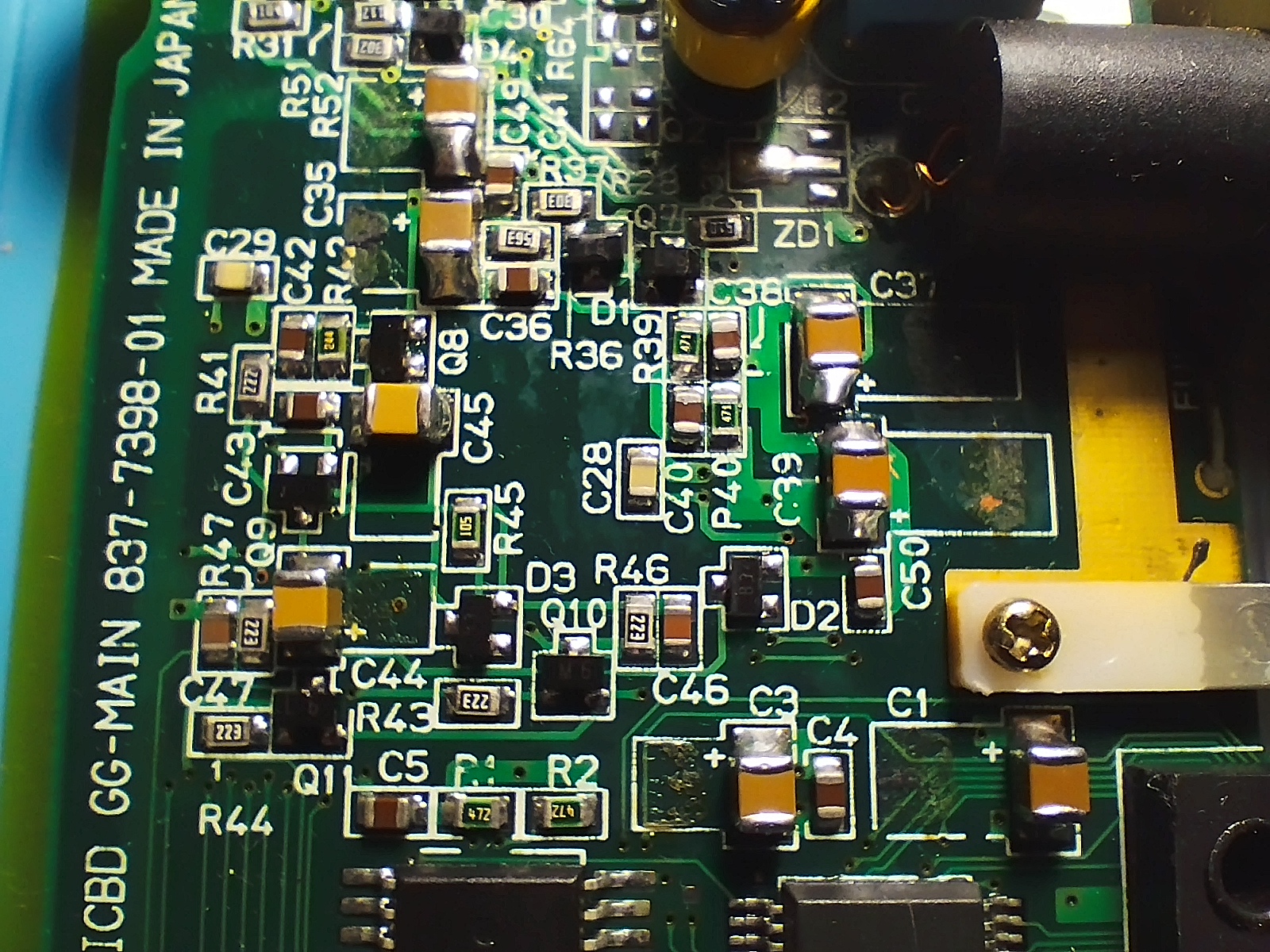
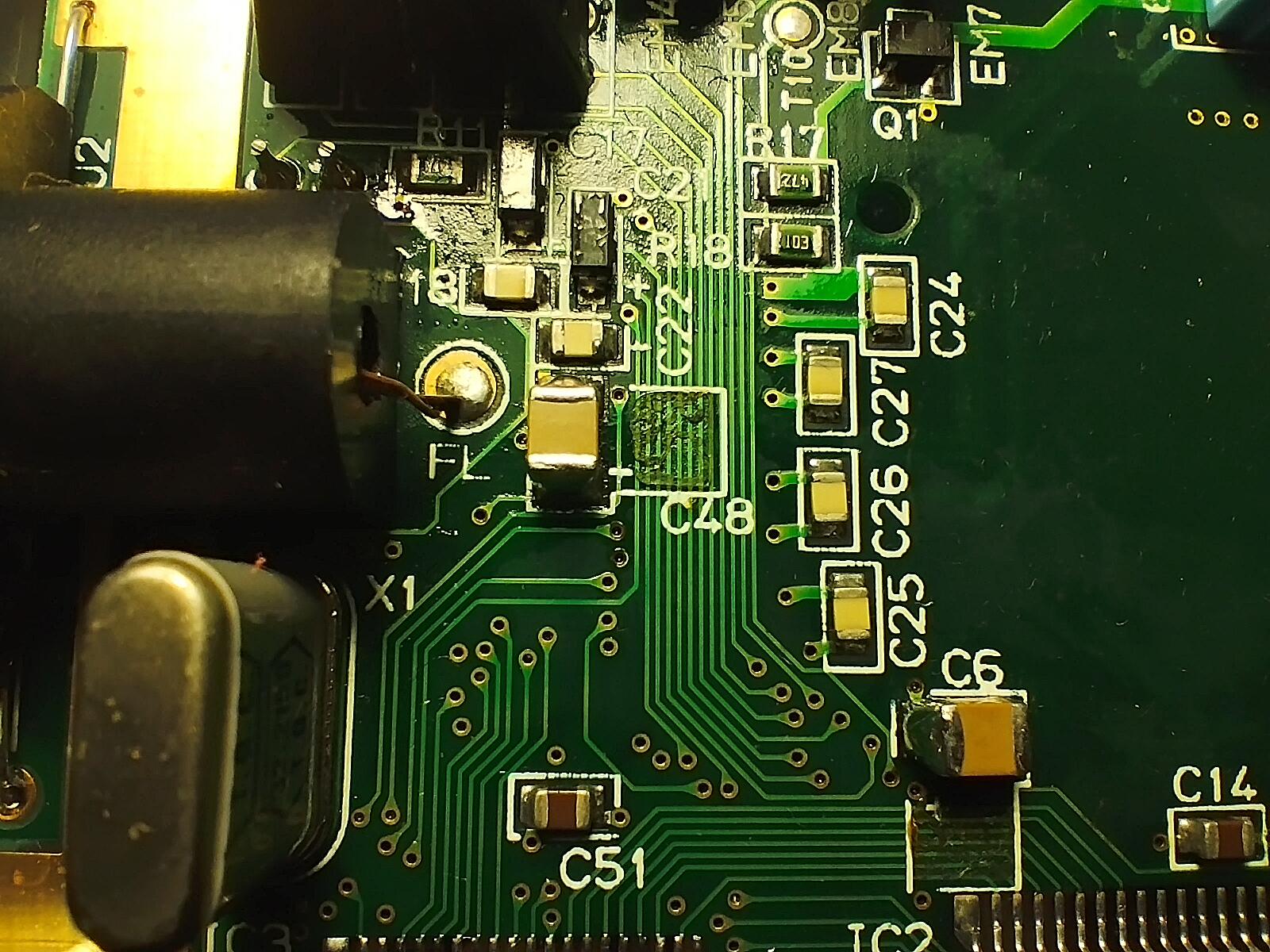
The soldering technique used this time consisted on the following steps:
- Tin one of the pads
- Pin one side of the capacitor to that pad
- After that apply solder to the other side
- Once done, rework the first pad by applying additional solder and adjusting the capacitor by applying heat to both pads if necessary
- Use a pair of tweezers to secure the capacitor in place while applying heat
Battery contacts
The battery contacts have been soaked in white vinegar to remove as much corrosion as possible. The results are far from perfect as now they are rusted, but still functional:
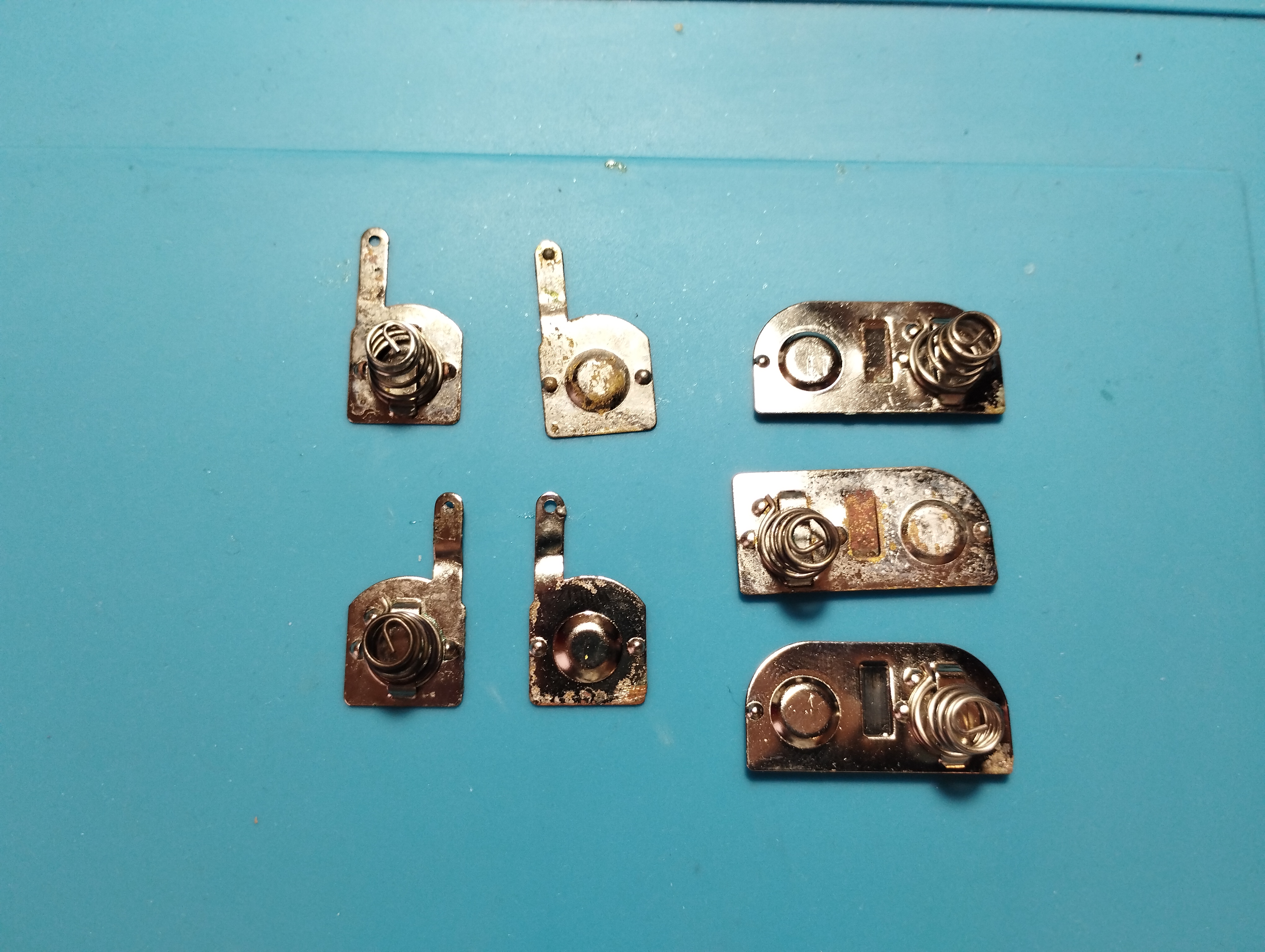
Connection cables have been replaced. Original ones didn’t stick when applying new solder.
Operation verification
All verifications except battery ones are done with a SEGA Mega Drive power supply (Model no. 1602-18, 10V - 1.2A).
Red Light Boot state
- Console enters the Red Light Boot state, required for further troubleshooting and repairs
- Voltage levels are slightly higher than the ones specified in the previous Wiki, but the console run games without issues
Audio
- Audio board works, both the speaker output and the output jack
Screen
- LCD screen turns on and the fluorescent tube lights up.
- Brightness can’t be adjusted with the Bright wheel
- The game image is very dim and visual artifacts appear when spinning the brightness wheel, such as light bands coming from top to bottom, like a scanning light, or vertical lines
- Checking the resistance values of the brightness wheel (VR1 should be 20kΩ) shows that it is busted: its value is ~45kΩ and there are no changes when turning it up or down. Replacing it with a 10kΩ potentiometer proves that the issue is indeed in the brightness wheel
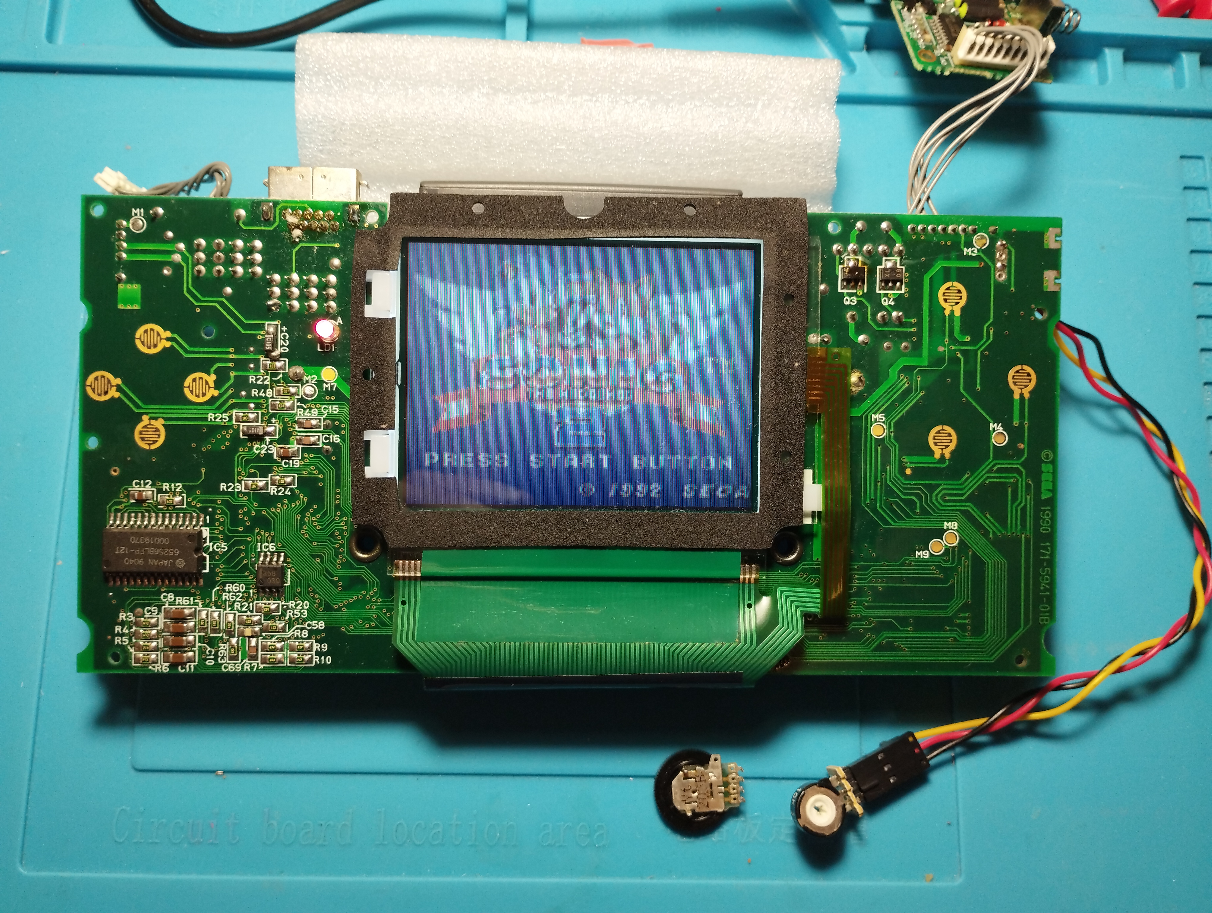
- SOLUTION: The brightness wheel has been replaced with the one from B0097296 as this console can be used as a donor one due to all its issues
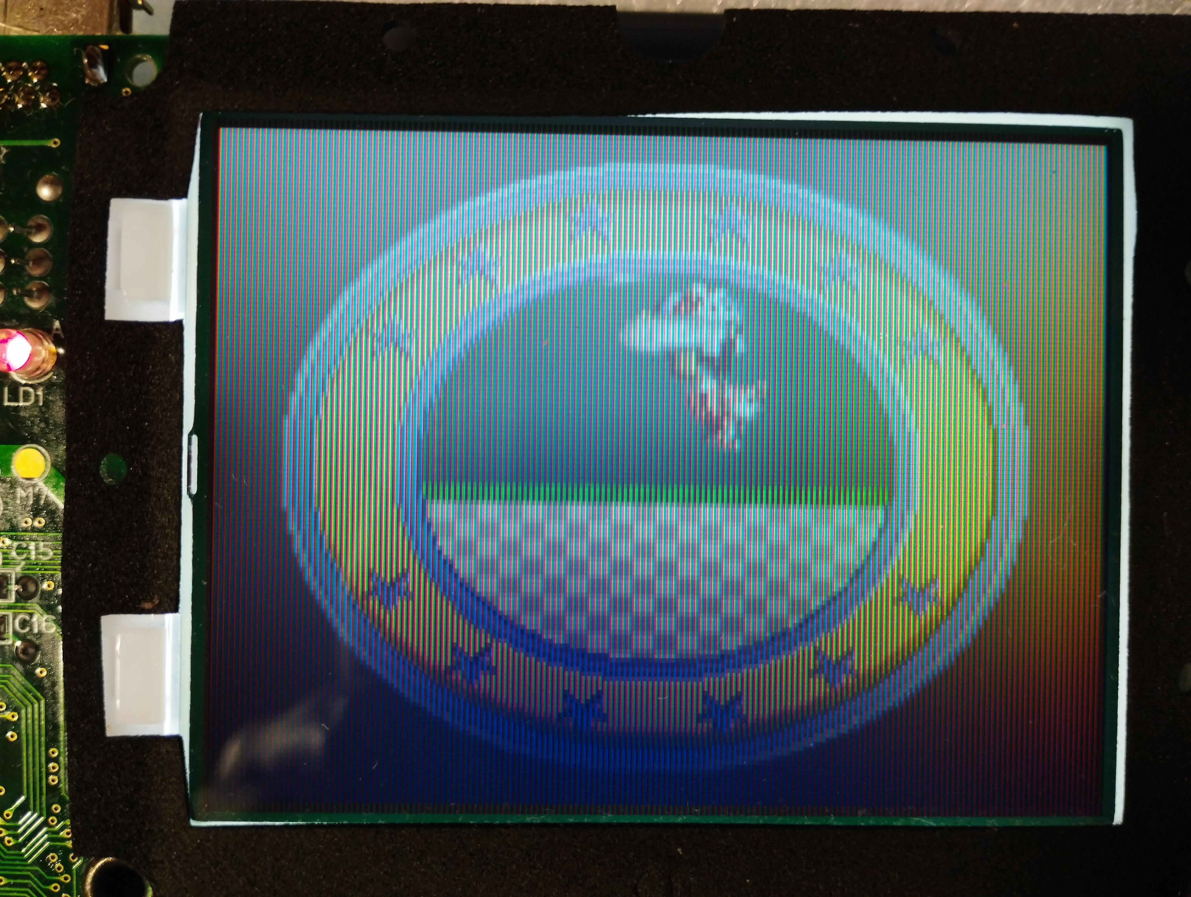
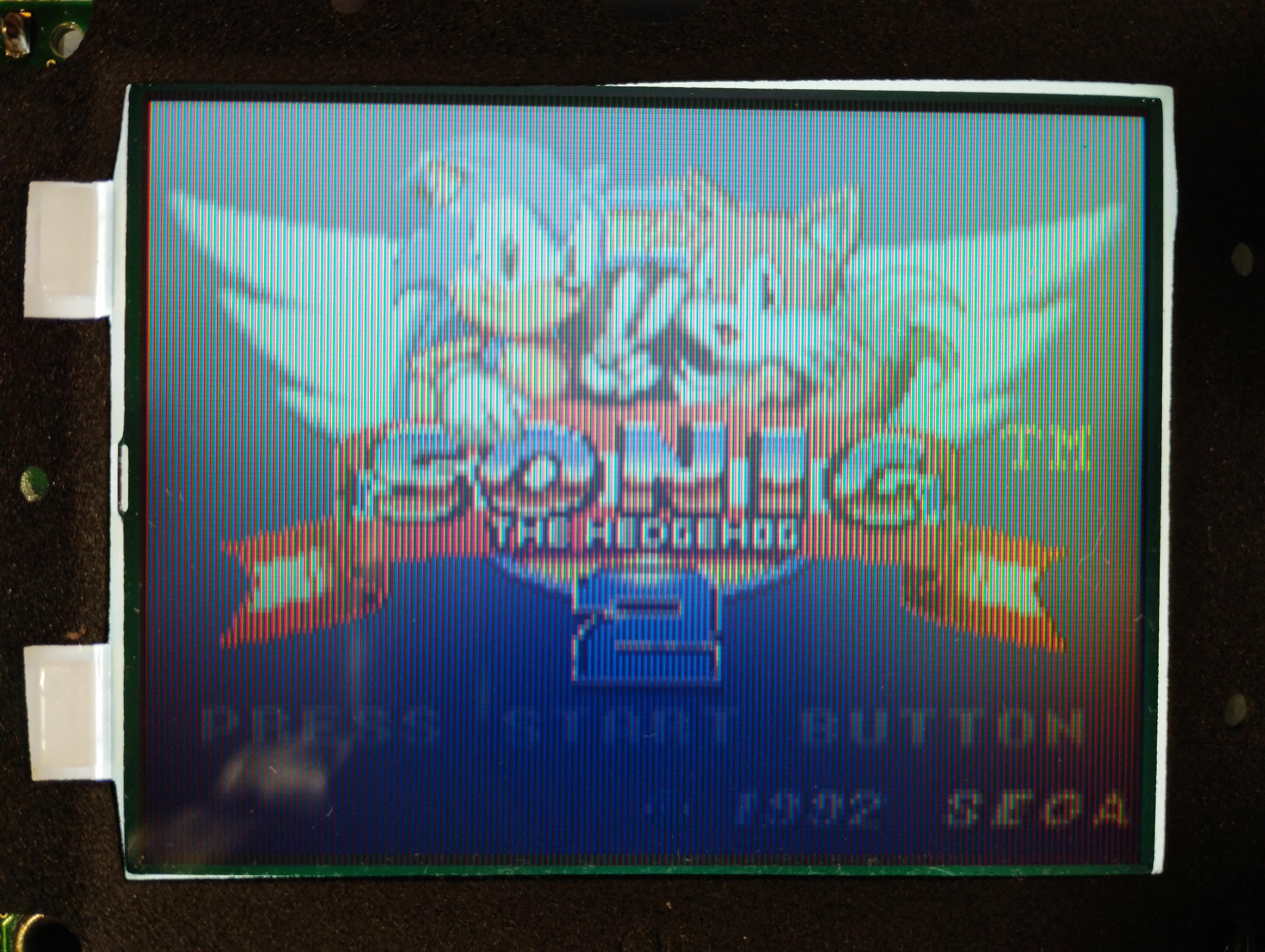
- Now image brightness can be properly adjusted, but it isn’t homogeneous on all the screen: there’s a clear central vertical band that shows less brightness than the left and right side of the screen
- Also, once the console is reassembled, the brightness wheel touches the shell, thus being a little bit hard to turn. On next maintenance, the wheel should be soldered as flat as possible to the board to avoid this
State on stable boot
- Console enters the Red Light Boot state, required for further troubleshooting and repairs
- Voltage levels are slightly higher than the ones specified in the previous Wiki, but the console run games without issues
- Audio board also works, both the speaker output and the output jack
- Incorrect brighness in central vertical section of the screen
- The brightness wheel touches the shell, thus being a little bit hard to turn. On next maintenance, the wheel should be soldered as flat as possible to the board to avoid this
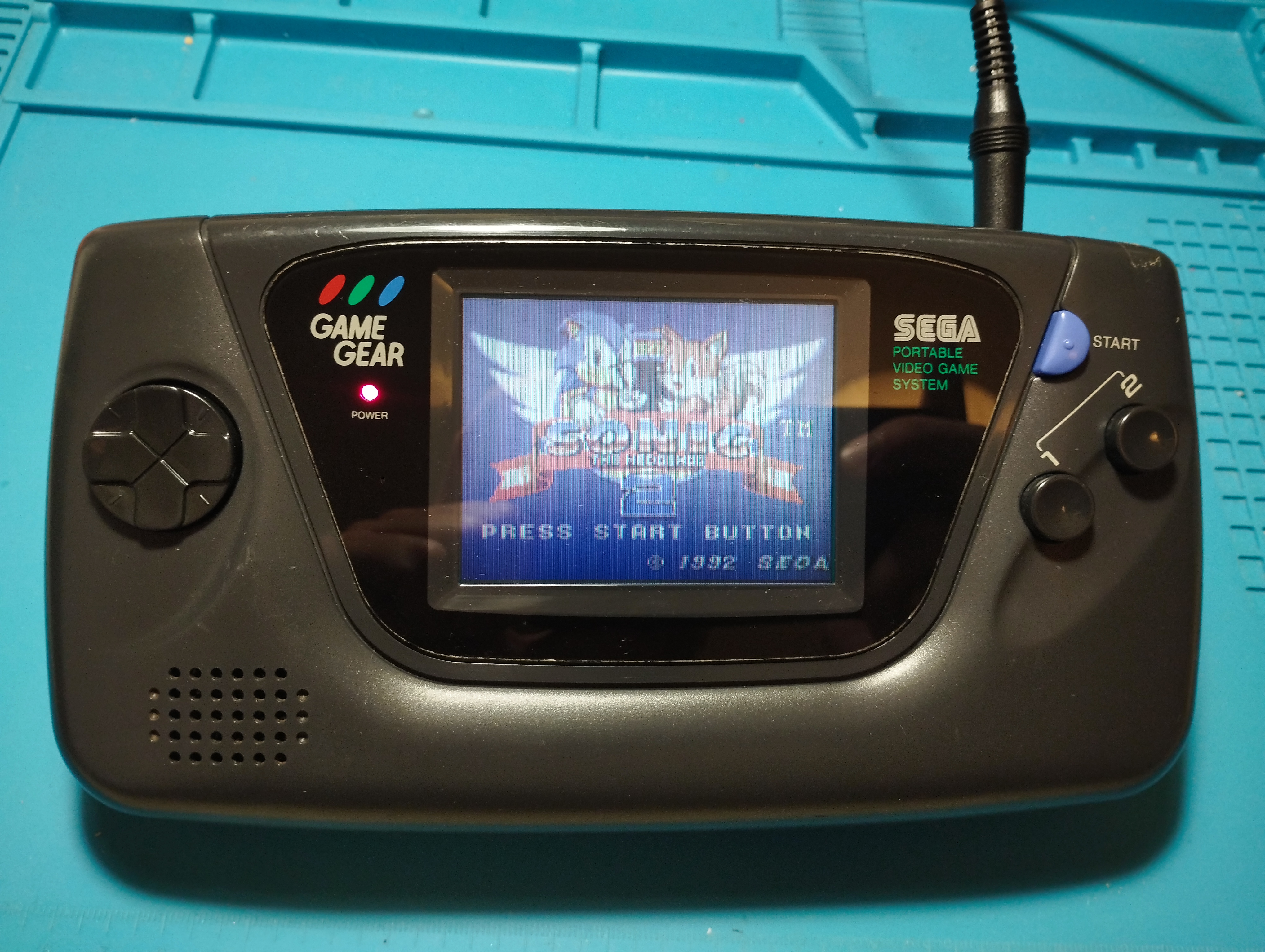
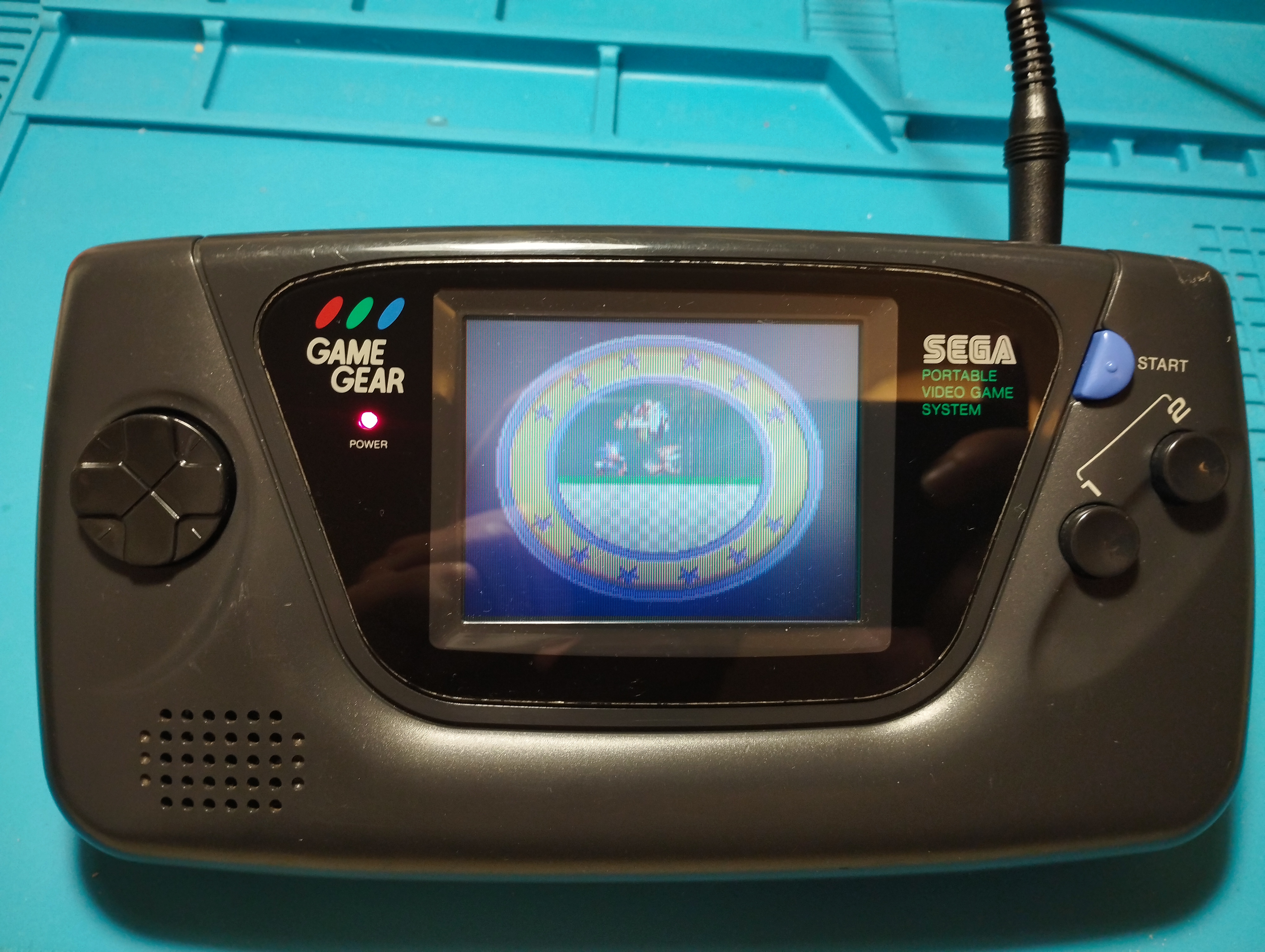
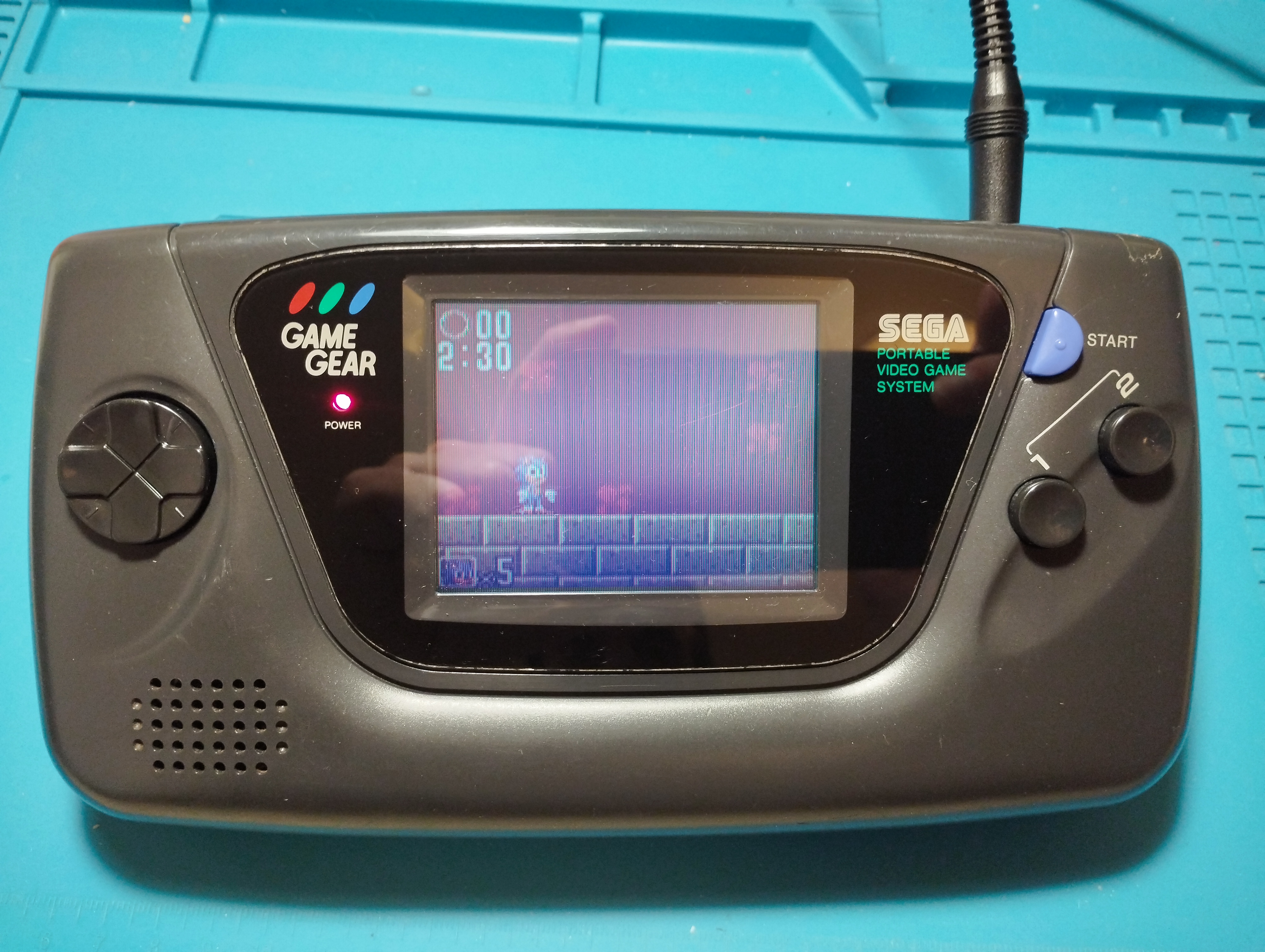
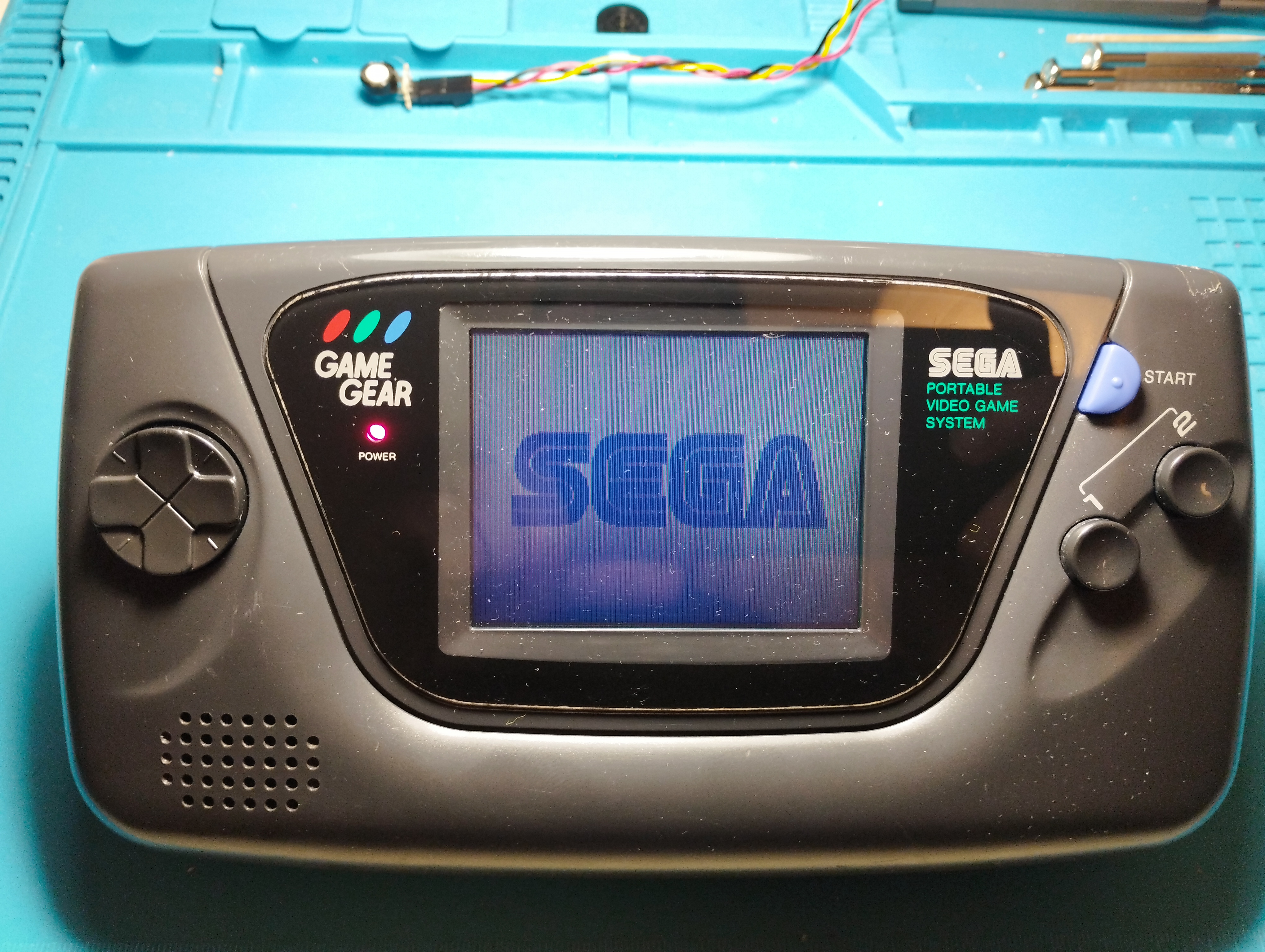
- After a three-hour session, the console operation is stable
Repairing time
- 12 hours
2024/06/24
Power LED always blinking
- After opening the console to use its power and audio boards for tests with B0097296, now it always shows a blinking power LED, either with a power supply or batteries. According to Retrosix, this should only happen when the console runs on low batteries. A new check on voltage values is required.
2025/04/25
Repairing time
- 2 days
Ruling out power board harness issues
- Unit tested with three different power boards and two different wall bricks:
All voltages are within specs (5V, VRef, VRes, VOnOff, VBat and 34V).
Bypassed power harness to rule out issues with the wires, LED always blinks:
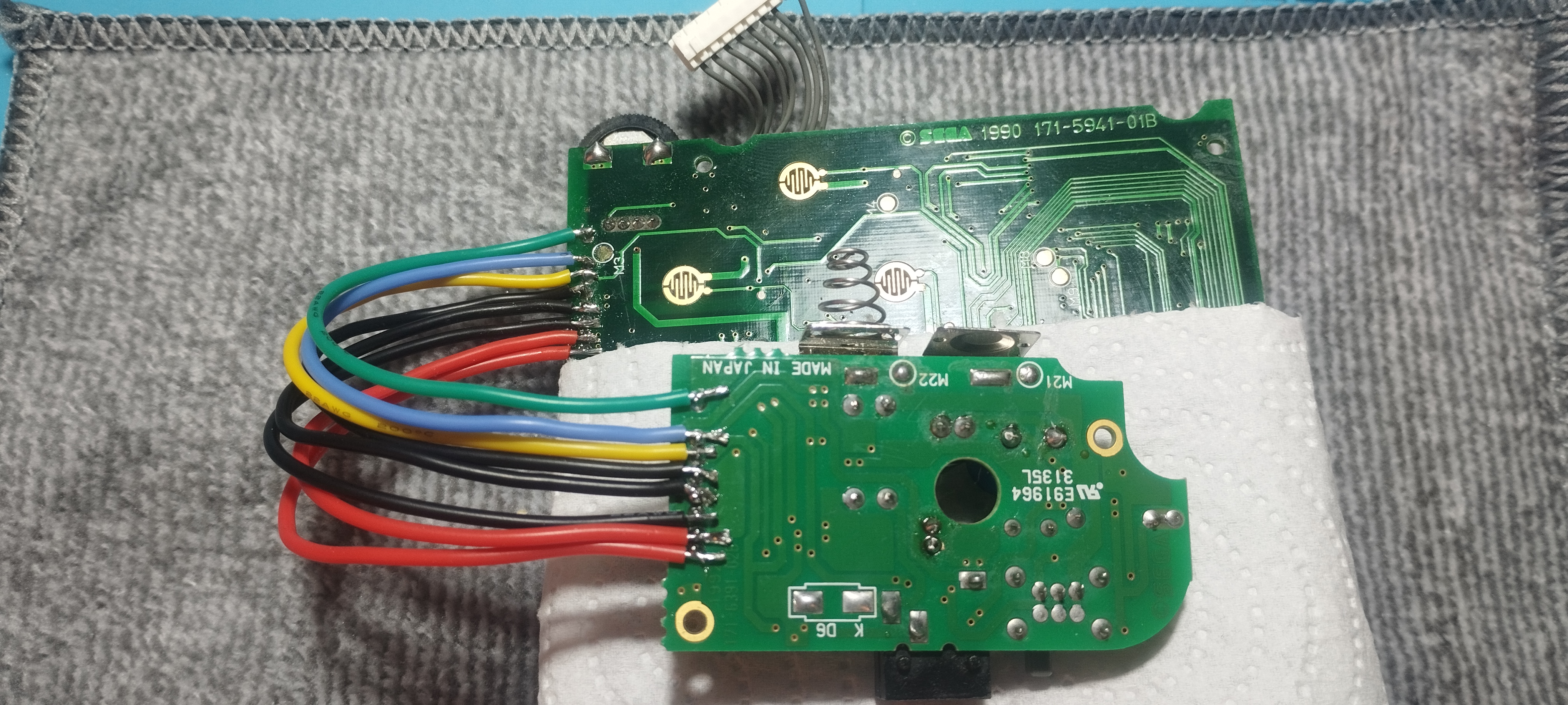
Game Gear - Power board harness bypassed Bypassed power harness to rule out issues with the wires AND VRef disabled from power board and grounded on main board, LED stops blinking:
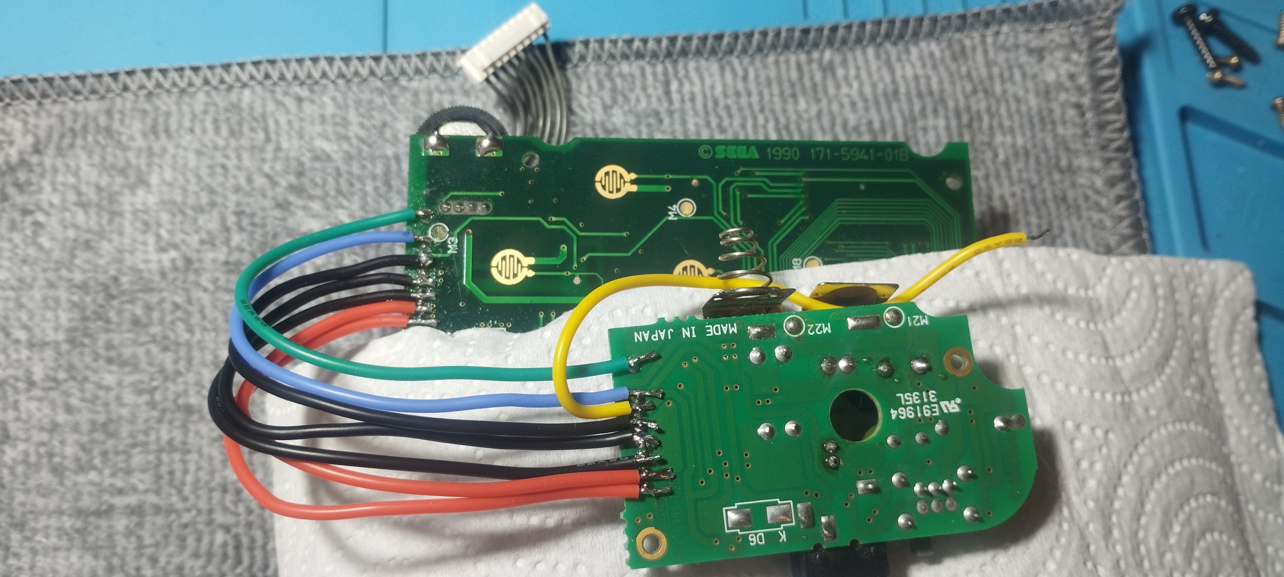
Game Gear - Power board VRef disabled and grounded
Workaround for power LED always blinking
- VRef signal coming from the power board disabled in the GG main board and grounded. Left ASIC internal voltage comparator is busted.
- This prevents low-battery indicator to work but at least LED isn’t always blinking.
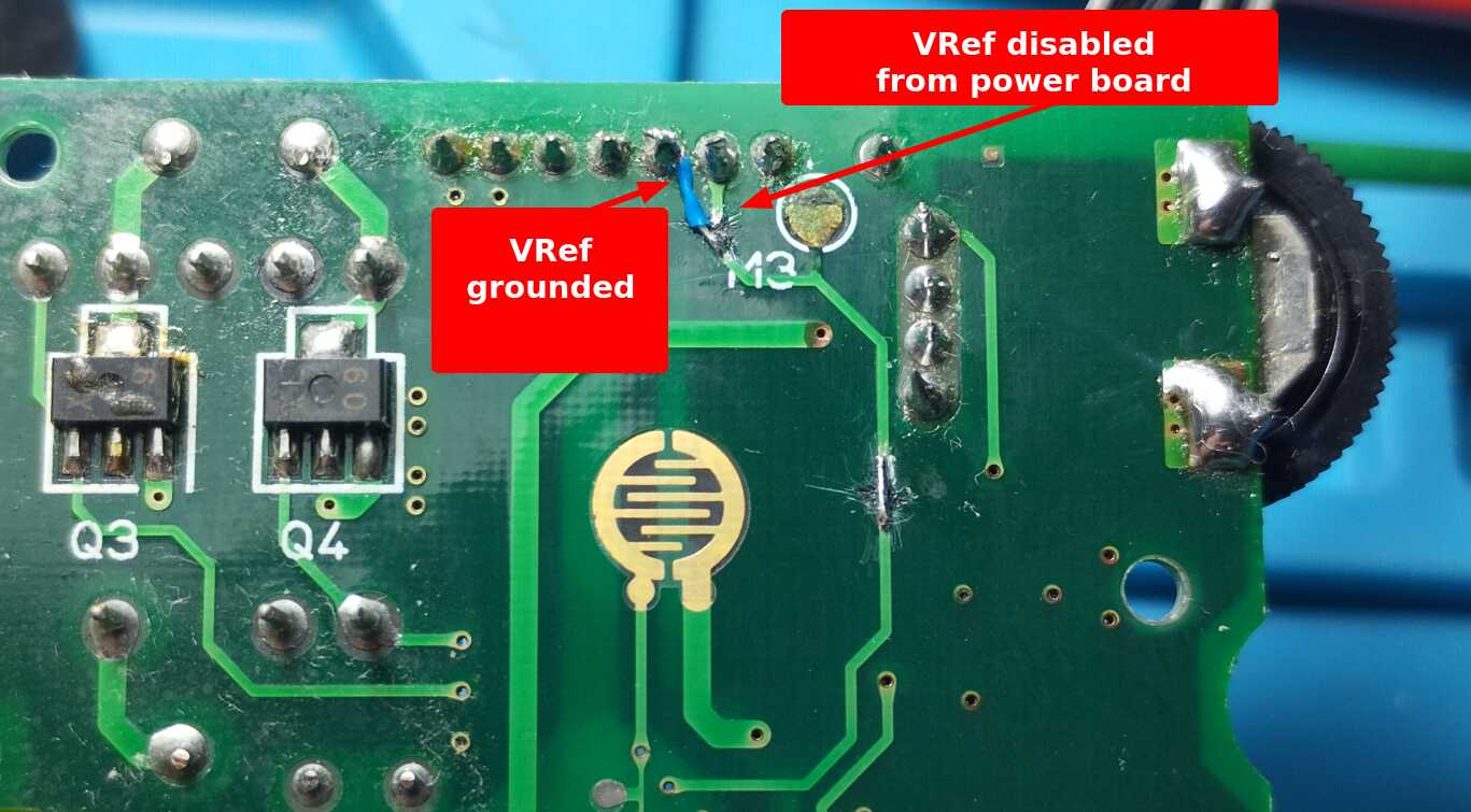
Game Gear - VRef workaround
Flatten brightness wheel
- Resoldering the brightness wheel and pushing it as much as possible to the board has ensured that it doesn’t touch the upper shell anymore.
Left ASIC encapsulation has cracks
This is a probable proof of its internal voltage comparator being broken. Pictures of the board before and after recapping show that these weren’t there initially, but the cause of them is unknown:
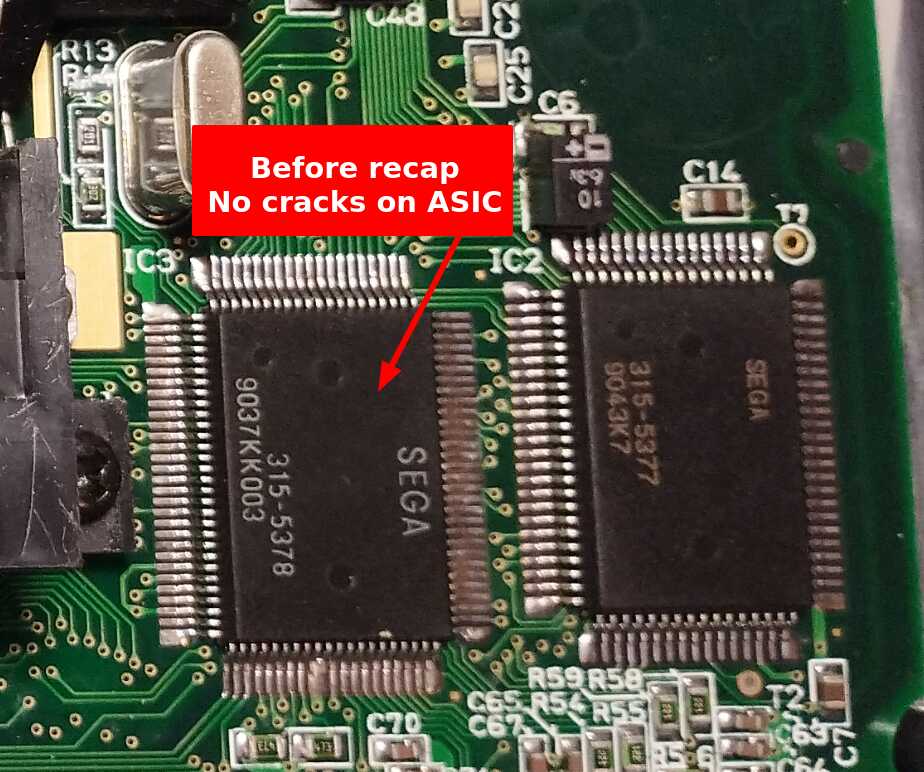
Game Gear - ASICs before recapping 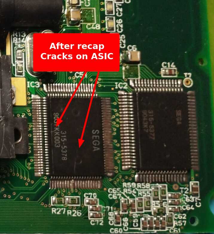
Game Gear - ASICs after recapping, visible cracks on the surface
Next steps
Screen replacement
- Of all the repaired Game Gears, this is the one with the best original screen, but due to the brightness issue (and if any of the pending Game Gears to repair has a better LCD) this console might be a good candidate to install a modern screen.
- Recent fixes on the board have shown that the left ASIC is partially damaged (voltage comparator not working), so this might not be the best console where to invest on modern replacements if the custom chips aren’t in perfect conditions.